

Sheet takeout device
- Summary
- Abstract
- Description
- Claims
- Application Information
AI Technical Summary
Benefits of technology
Problems solved by technology
Method used
Image


Examples
first embodiment
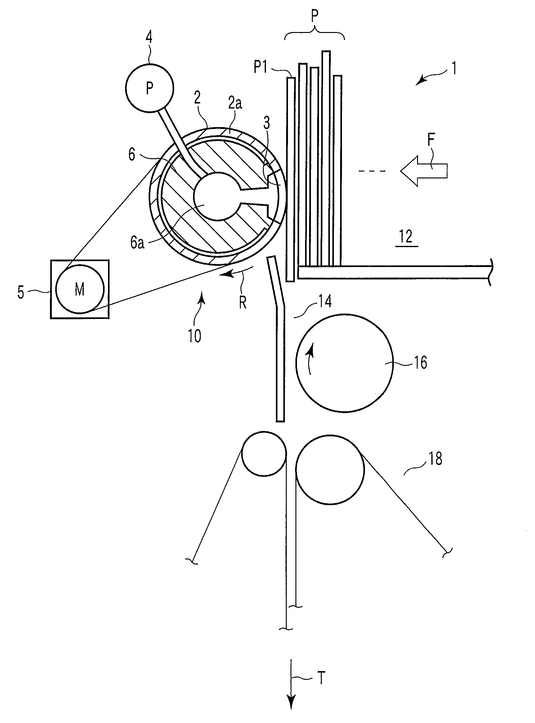
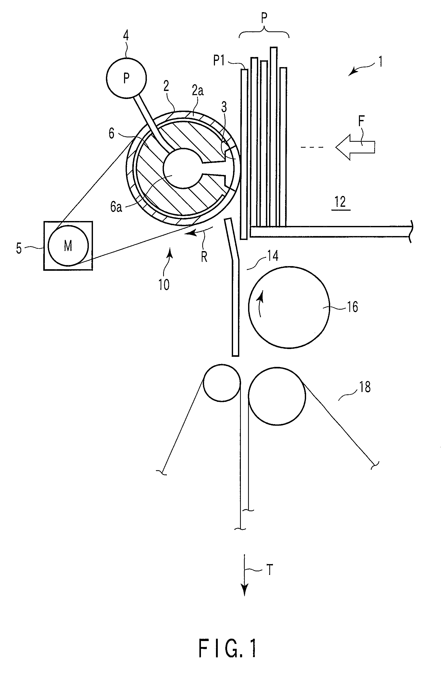
[0038]FIG. 1 shows a schematic plan view of a sheet takeout device 1 according to the present invention (hereinafter simply referred to as a takeout device 1). FIG. 2 is an enlarged view of a suction port 3 in a takeout roller 2 incorporated in the takeout device 1. FIG. 3 is an example of a velocity diagram showing a speed at which the takeout roller 2 is intermittently rotated.
[0039]As shown in FIG. 1, the takeout device 1 has a loading section 12 on which a plurality of collected sheets P such as mail or bills which are to be processed are loaded in an upright position, a supply mechanism (not shown) which moves the loaded sheets P in a collecting direction (the direction of arrow F in FIG. 1) and which feeds a first sheet P1 located at a moving-direction leading end of the sheets P, to a takeout position, a takeout mechanism 10 that takes out the sheet P1 fed to the takeout position, in a surface direction (the direction of arrow T in FIG. 1), a separating mechanism 16 that appl...
fourth embodiment
[0085]For example, FIG. 15(a) is a schematic plan view of an essential part of a takeout mechanism 40 according to the present invention corresponding to the takeout mechanism 10 according to the present embodiment, described above, in which the takeout roller 2 is replaced with a takeout belt 42. FIG. 15(b) is a side view of the essential part of the takeout mechanism 40 as viewed from the takeout position. The takeout belt 42 is wound and extended around a plurality of rollers 41 and is allowed to travel endlessly along the sheet P located at the takeout position. A negative pressure chamber 44 is located opposite the sheet P located at the takeout position, across the takeout belt, that is, the negative pressure chamber 44 is located inside the takeout belt 42. The negative pressure chamber 44 is fixedly mounted with an opening 46 facing the takeout position.
[0086]A suction port 48 is formed in the takeout belt 42 and passes by the opening 46 in the negative pressure chamber 44 w...
sixth embodiment
[0092]FIG. 21 shows a variation of the sixth embodiment, described above. This takeout mechanism 60′ has a suction port 67 with a large number of holes with different aperture areas instead of the triangular suction port 63 in the takeout mechanism 60, described above. The takeout mechanism 60′ can function similarly to the takeout mechanism described with reference to FIG. 13 and exert effects similar to those of the takeout mechanism described with reference to FIG. 13.
[0093]As described above, even if the takeout belt is used as a rotating member that contacts the sheet P located at the takeout position, effects can be exerted which are similar to those exerted when the takeout roller is used. The takeout timing for the sheet P can be prevented from deviating, enabling the pitches or gaps between the sheets P to be stabilized. The sheet P can also be prevented from being stained or damaged as a result of a difference in speed between the belt and the sheet P.
PUM
 Abstract
Description
Claims
Application Information