Printing element substrate, printhead, and printing apparatus

Active Publication Date: 2018-03-29
CANON KK
View PDF2 Cites 3 Cited by
  • Summary
  • Abstract
  • Description
  • Claims
  • Application Information

AI Technical Summary

Benefits of technology

[0005]With the above problems in mind, the present invention has been made. It is an object of the present invention to provide a highly reliable printing apparatus that includes a

Problems solved by technology

Therefore, it is more difficult to synchronize such a clock signal and data signal with each other.
In the technique disclosed in International Publication No. 2012/102709, it is necessary to check the result of reception performed by the printing element substrate a plurality of times in orde

Method used


Image

  • Printing element substrate, printhead, and printing apparatus
  • Printing element substrate, printhead, and printing apparatus
  • Printing element substrate, printhead, and printing apparatus

Examples


Example

[0048]FIG. 3 is a diagram schematically showing a printing apparatus 100 according to a first embodiment of the present invention. FIG. 3 shows an example of the full-line printhead 101. The same parts are hereinafter designated by the same reference characters. If the same parts need to be identified separately, these parts are designated by the same reference characters with different symbols affixed thereto. In this embodiment, the printhead 101, which includes a plurality of printing element substrates 103 (103-1 to 103-n), is coupled to a main-body substrate 102 of the printing apparatus through a transmission line path 110.

[0049]The printing element substrates 103 each include a first receiver circuit 106 for receiving a first signal 111 (DATA), a second receiver circuit 107 for receiving a second signal 112 (CLK), and a third receiver circuit 108 for receiving a third signal 113. The printing element substrates 103 also each include a correction circuit 105, and a driving cir...

Example

SECOND EMBODIMENT

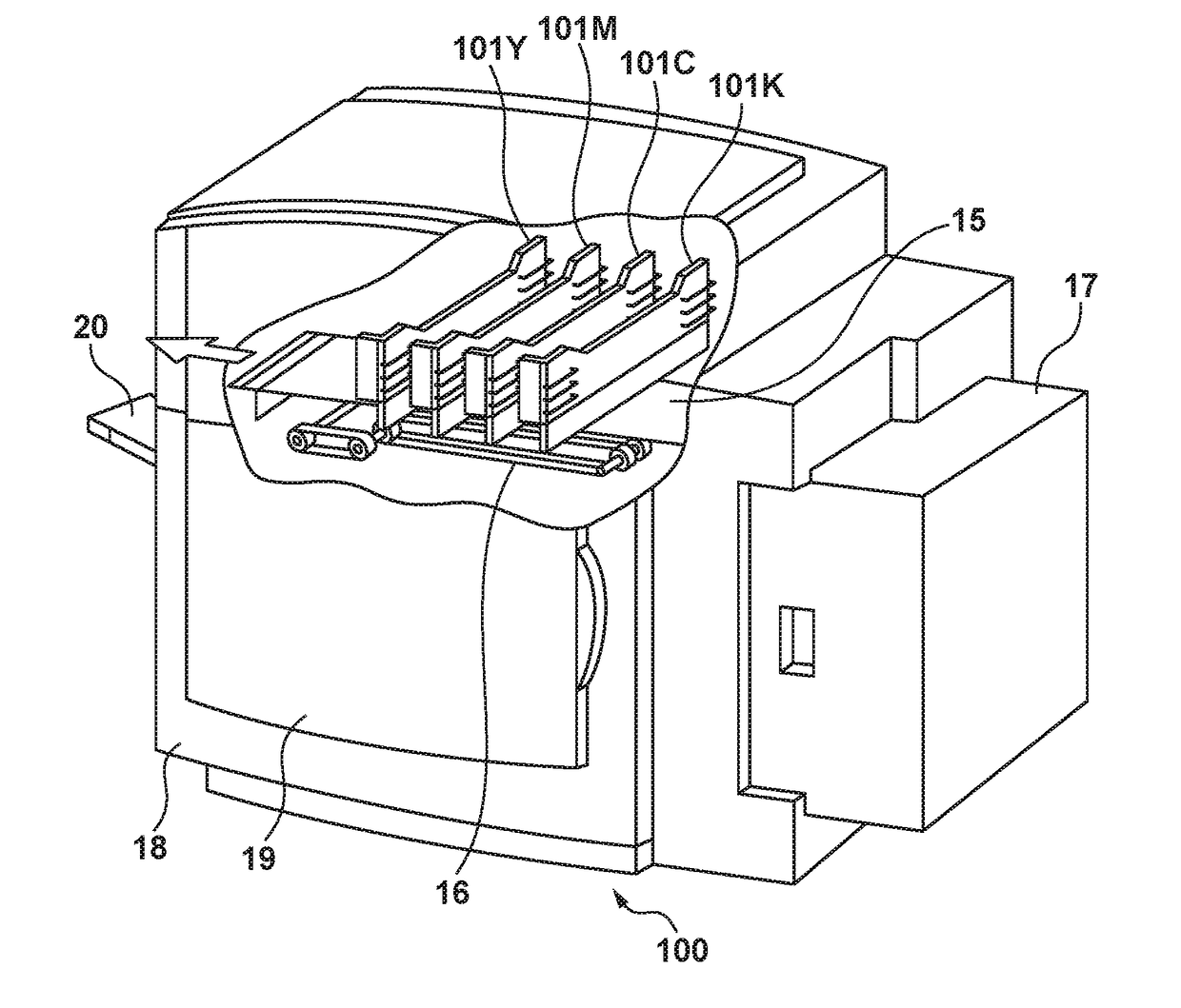
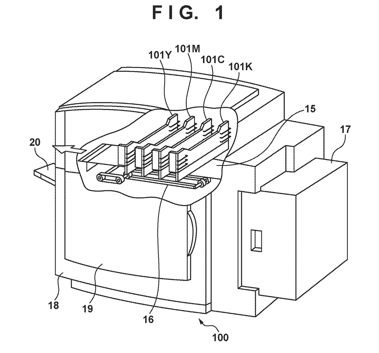
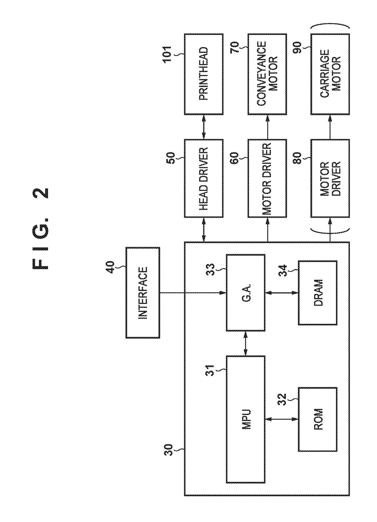
[0068]FIG. 12 is a diagram schematically showing a printing apparatus 500 according to a second embodiment of the present invention. The printing apparatus 500 according to the second embodiment is different from the printing apparatus 100 according to the first embodiment in that printing element substrates 503 each include a temperature detection unit 504. The temperature detection unit 504 outputs a temperature detection signal 505 corresponding to temperature to the head control IC 109 provided in the main-body substrate 102 of the printing apparatus through the transmission line path 110. The head control IC 109 reads (samples) the temperature detection signal 505 to find a temperature state of the printing element substrate 503, and on the basis of the temperature state, controls a printhead 501, such as changing conditions (a driving voltage or a driving pulse) for driving a printing element, etc.

[0069]As in the first embodiment, the correction circuit 105 co...


PUM


Abstract

A printing element substrate comprises a correction circuit that corrects a phase difference between a first signal and a second signal, wherein the correction circuit includes a first delay circuit that generates a plurality of first delayed signals having different delay times with respect to the first signal, and a second delay circuit that generates a plurality of second delayed signals having different delay times with respect to the second signal, the correction circuit specifies a phase of the first signal to be output to the driving circuit, on the basis of comparison between the plurality of first delayed signals and the second signal, and the correction circuit specifies a phase of the second signal to be output to the driving circuit, on the basis of comparison between the plurality of second delayed signals and the first signal having the specified phase.

Description

BACKGROUND OF THE INVENTIONField of the Invention[0001]The present invention relates to printing element substrates, printheads, and printing apparatuses.Description of the Related Art[0002]A printing element substrate in an inkjet printing apparatus, which includes a semiconductor integrated circuit, receives a clock signal (CLK) and an image data signal (DATA) from the main body of the printing apparatus, and performs a printing operation on the basis of the image data. A recent increase in printing speed has been accompanied by clock signals and image data signals having a frequency of as high as several hundreds of megahertz. A phase difference occurs between a clock signal and an image data signal due to variations in a transmitter circuit and a receiver circuit. A clock signal and an image data signal that have a higher frequency are more likely to be significantly affected by the phase difference. Therefore, it is more difficult to synchronize such a clock signal and data sig...

Claims


Application Information

Patent Timeline
IPC IPC(8): B41J2/045
CPCB41J2/04563B41J2/04541B41J2/04508B41J2/04573B41J2/07B41J2/04543
Inventor UMEDA, KENGO
Owner CANON KK
Why Eureka
Try Eureka