Relay driver circuit

Inactive Publication Date: 2011-10-06
YAMATAKE HONEYWELL CO LTD
View PDF1 Cites 1 Cited by
  • Summary
  • Abstract
  • Description
  • Claims
  • Application Information

AI Technical Summary

Benefits of technology

[0013]The present invention is able to achieve stabilized operation as a result of reducing the ripple component in the voltage between the relay terminals due to the ability to provide an adequate relay driving current through modulating, based on a control signal from the outside, the power that is supplied to the primary coil of a transformer, from a DC power supply that is connected to the DC power supply, and the power that is induced between the terminals of the secondary coil of the transformer is supplied to an electromagnetic relay that is provided with a mechanical contact point.
[0014]Furthermore, it is possible to increase the power efficiency through the ability to provide power to the relay without charging / discharging the capacitors by turning the transistor ON / OFF based on a control signal. Since the power is supplied to the relay by a transformer through modulating, based the control signal, the power that is supplied to the primary coil of the transformer is all that is required.
[0015]Moreover, the double isolation between the device that is being driven using the relay (the load) and the DC power supply, through the use of the transformer and the electromagnetic relay, makes it possible to minimize the effects on the DC power supply side even if a fault were to occur in the load, resulting in the ability to provide a stabilized circuit.

Problems solved by technology

However, in the circuit illustrated in FIG. 6, the ripple component of the voltage between the relay terminals is large due to the use of only the electric power stored in the capacitor as the driving power supply for the relay, making it difficult to satisfy ripple voltage tolerance specifications for the relay, causing the operation to be unstable.
Additionally, in the circuit illustrated in FIG. 5, it is necessary to provide electric power to both the capacitors C1 and C2 when turning the transistor Q2 ON, thus requiring extra electric power beyond the power supplied to the electromagnetic relay, resulting in a problem in that the power efficiency (the ratio of the output power to the input power) is poor.

Method used


Image

  • Relay driver circuit
  • Relay driver circuit
  • Relay driver circuit

Examples


Embodiment Construction

[0024]Forms exemplifying the present invention are explained in detail below in reference to the drawings.

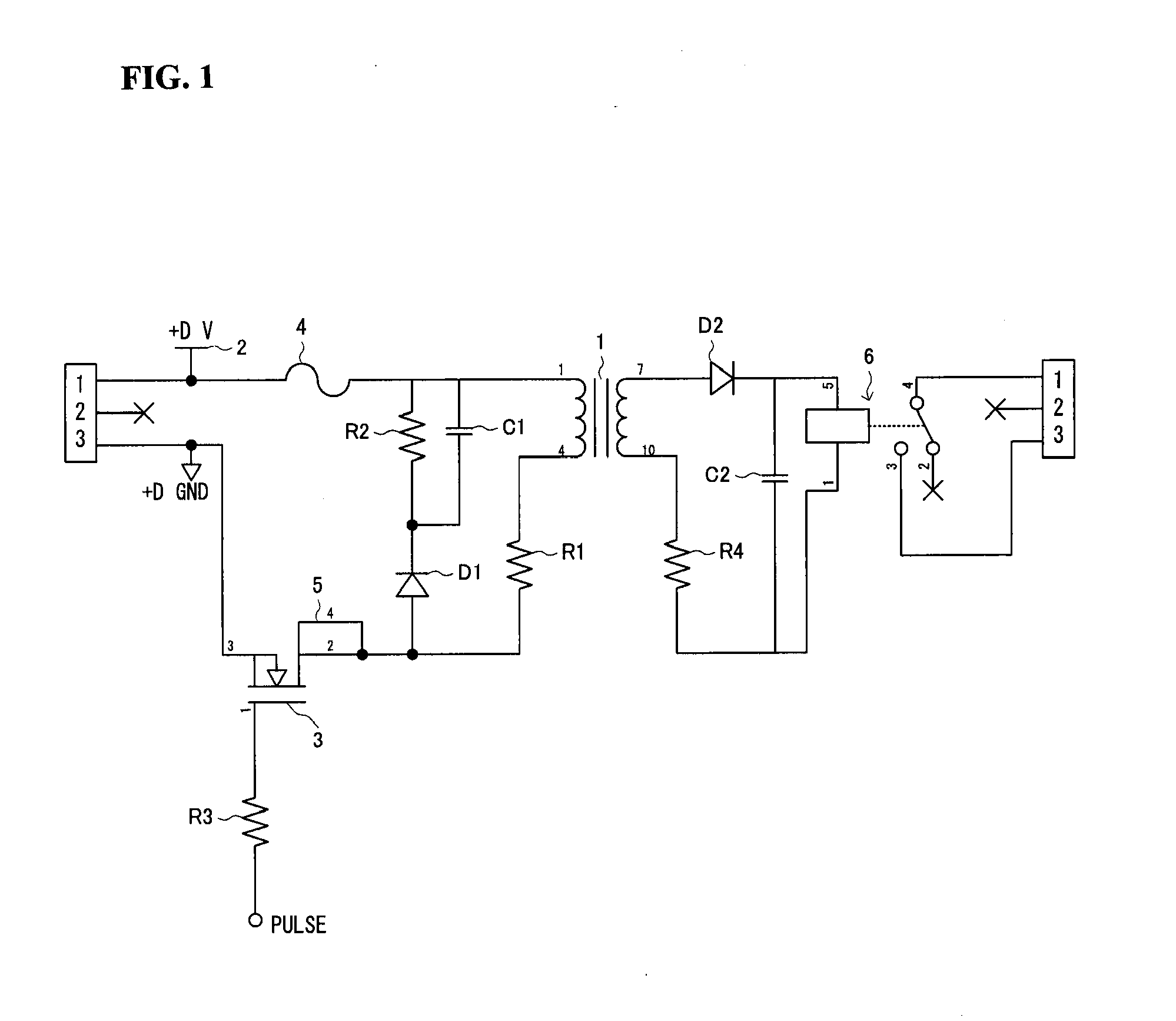
[0025]As illustrated in FIG. 1, the relay driving circuit according to an example of the present invention has a transformer 1; a circuit (primary-side circuit) that is connected to the primary-side coil of the transformer 1; and a circuit (secondary-side circuit) that is connected to the secondary side coil of the transformer 1.

[0026]A DC power supply 2 is connected in series with the primary-side circuit. Additionally, a switching element 3, a fuse 4, a feedback circuit 5, and a resistor R1 are connected in series between the transformer 1 and the DC power supply 2, and a diode D1, and a resistor R2 and a capacitor C1, which are each connected in series with the diode D1, are connected in parallel between the transformer 1 and the DC power supply 2. A pulse signal from a microcontroller is inputted into the switching element 3 through a resistance R3.

[0027]In the secondary-sid...


PUM


Abstract

Power that is supplied to a primary coil of a transformer from a DC power supply that is connected to the primary coil is modulated based on continuous pulses supplied from a microcontroller, and power that is induced between terminals of a secondary coil of the transformer is supplied to a relay. A large driving current can be supplied to the relay thereby, thus making it possible to reduce the ripple component, and, as a result, to achieve stabilized operation.

Description

CROSS REFERENCE TO RELATED APPLICATIONS[0001]The present application claims priority under 35 U.S.C. § 119 to Japanese Patent Application No. 2010-079486, filed Mar. 30, 2010, which is incorporated herein by reference.FIELD OF TECHNOLOGY[0002]The present invention relates to a relay driving circuit for driving an electromagnetic relay.BACKGROUND OF THE INVENTION[0003]Electromagnetic relays are used more often than semiconductor relays for safety relays in combustion furnaces. This is because the ability to withstand noise and the ability to withstand the environment, which are the distinctive features of the electromagnetic relay, are more important than rapid response time and long service life, which are the distinctive features of semiconductor relays. Conventionally, circuits that use capacitors, as illustrated in FIG. 5 and FIG. 6, have been used as circuits for driving electromagnetic relays safely (See, for example, Unexamined Japanese Patent Application Publication 1108-1453...

Claims


Application Information

Patent Timeline
IPC IPC(8): H01H47/18H01H47/22
CPCH01H47/325H01H47/32
Inventor AKITA, DAISUKEKUMAZAWA, YUUICHI
Owner YAMATAKE HONEYWELL CO LTD
Why Eureka
Try Eureka