Method for determining location of phase-to-earth fault

a phase-to-earth fault and location technology, applied in the field of single-phase earth fault location, can solve the problems of deteriorating the accuracy of a calculated fault location estimate, especially challenging distribution networks, and difficult fault localization, so as to improve the tolerance for load current, improve the accuracy of fault localization, and improve the effect of fault location

Active Publication Date: 2008-12-04
ABB (SCHWEIZ) AG
View PDF13 Cites 24 Cited by
  • Summary
  • Abstract
  • Description
  • Claims
  • Application Information

AI Technical Summary

Benefits of technology

[0008]An advantage of the invention is that the accuracy of fault localization can be improved. More accurate fault location can be obtained due to realistic modeling of the loading of the electric line. In addition, the invention provides for an improved tolerance for load current.

Problems solved by technology

Localization of earth faults is a challenging task.
There are many factors which deteriorate the accuracy of a calculated fault location estimate, such as fault resistance and load.
Distribution networks are especially challenging as they have specific features which further complicate and challenge fault localization algorithms.
Their performance has proven to be satisfactory in localizing short-circuit faults, but they are often not capable of localizing low current earth faults, i.e. earth faults in high impedance earthed systems.
The disclosed method is based on measurements in a substation supply bay and it cannot therefore be optimally applied to feeder bays.
With actual disturbance recordings one could expect even larger errors.
In real medium voltage feeders this assumption is rarely correct.
In such cases, the accuracy of prior art fault localization algorithms is impaired.

Method used


Image

  • Method for determining location of phase-to-earth fault
  • Method for determining location of phase-to-earth fault
  • Method for determining location of phase-to-earth fault

Examples


Embodiment Construction

[0014]The application of the invention is not limited to any specific system, but it can be used in connection with various three-phase electric systems to determine a location of a phase-to-earth fault on a three-phase electric line of an electric network. The electric line can be a feeder, for example, and may be an overhead-line or a cable or a combination of both. The electric power system in which the invention is implemented can be an electric transmission or distribution network or a component thereof, for example, and may comprise several feeders. Moreover, the use of the invention is not limited to systems employing 50-Hz or 60-Hz fundamental frequencies or to any specific voltage level.

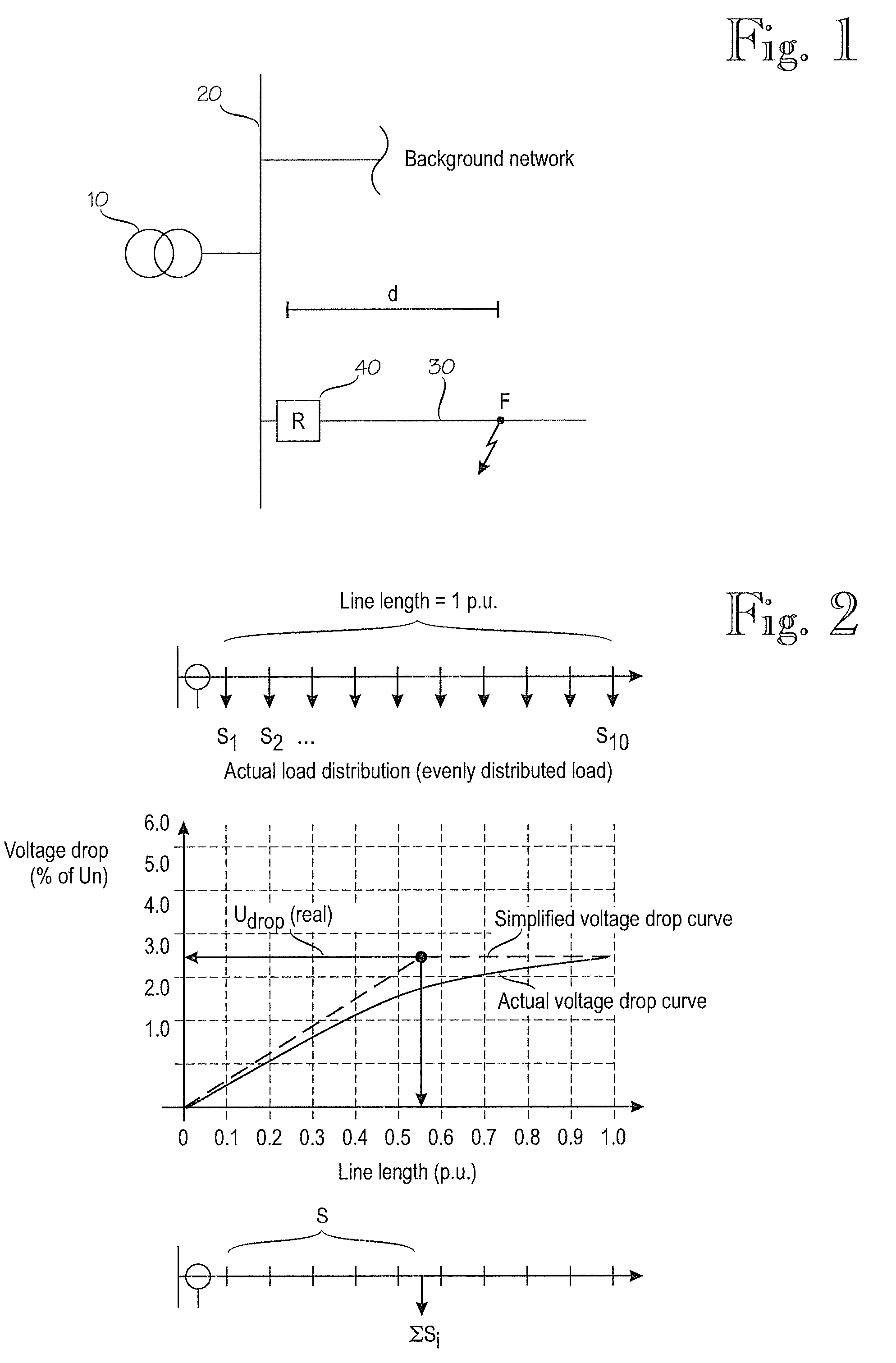
[0015]FIG. 1 is a simplified diagram illustrating an electric network in which the invention can be applied. The figure shows only the components necessary for understanding the invention. The exemplary network can be a medium voltage (e.g. 20 kV) distribution network fed through a substatio...


PUM


Abstract

A method and apparatus for determining a location of a phase-to-earth fault on a three-phase electric line of an electric network, comprising determining, when the ratio of a fault current and load current has a first value, a first fault distance line which indicates an estimate of a distance of the fault from the measuring point in relation to an equivalent load distance, determining, when the ratio of the fault current and load current has a second value which differs from the first value, at least one second fault distance line, determining a distance at which the determined fault distance lines intersect when superimposed and determining the distance between the measuring point and the point of fault on the basis of the determined distance or distances of intersection.

Description

FIELD OF THE INVENTION[0001]The present invention relates to localization of single-phase earth faults in electric networks.BACKGROUND OF THE INVENTION[0002]Localization of earth faults is a challenging task. There are many factors which deteriorate the accuracy of a calculated fault location estimate, such as fault resistance and load. Distribution networks are especially challenging as they have specific features which further complicate and challenge fault localization algorithms. These include e.g. non-homogeneity of lines, presence of laterals and load taps.[0003]Impedance-based fault location algorithms have become industry standard in modern microprocessor-based protection relays. The reason for their popularity is their easy implementation as they utilize the same signals as the other functions. Their performance has proven to be satisfactory in localizing short-circuit faults, but they are often not capable of localizing low current earth faults, i.e. earth faults in high i...

Claims


Application Information

Patent Timeline
Patent Type & Authority Applications(United States)
IPC IPC(8): G01R31/08
CPCG01R31/088
Inventor WAHLROOS, ARIALTONEN, JANNE
Owner ABB (SCHWEIZ) AG
Why Eureka
Try Eureka