Particle Detector, System and Method

a particle detector and particle technology, applied in the field of particle detectors and methods, can solve the problems of difficult to use the above-mentioned methods of detecting particles in outdoor areas or very large indoor arenas, and the probability of particles passing out of the region is not guaranteed, so as to improve the detection of variations in images

Active Publication Date: 2008-12-04
GARRETT THERMAL SYST LTD
View PDF29 Cites 161 Cited by
  • Summary
  • Abstract
  • Description
  • Claims
  • Application Information

AI Technical Summary

Benefits of technology

[0074]masking a central portion of the detected beam so as to enhance the detection of variations in the images.

Problems solved by technology

As many buildings employ air handling means for extracting air from a region, such as air-conditioning, there is no guarantee that suspended particles will be detected rather than pass out of the region via the air handling ducts.
It can be very difficult to use the aforementioned methods of detecting particles in outdoor areas or very large indoor arenas where there may not be appropriate locations to place a point detector or a sample point and connecting tubing.
These detectors, namely beam detectors and the detector disclosed in Duston, have relatively low sensitivity and are only capable of measuring the total attenuation within the illuminated region.
In particular, such equipment may be intrusive to the monitored environment and may require complex connections, for example, wiring or otherwise to supply control, communications and power to the equipment.
Once installed and / or commissioned such equipment may be susceptible to environmental conditions that form part of the monitored environment that contribute to drift, misalignment and the like to cause inaccuracies of measurement.
Furthermore, there are environmental conditions and events unrelated to alarm conditions that may commonly occur in the monitored environment and may contribute to false alarms when detecting particles.
Nuisance particles such as airborne dust, for example, may be present in the monitored environment and cause false alarms to be raised when there is no actual threat of fire outbreak.

Method used


Image

  • Particle Detector, System and Method
  • Particle Detector, System and Method
  • Particle Detector, System and Method

Examples


Embodiment Construction

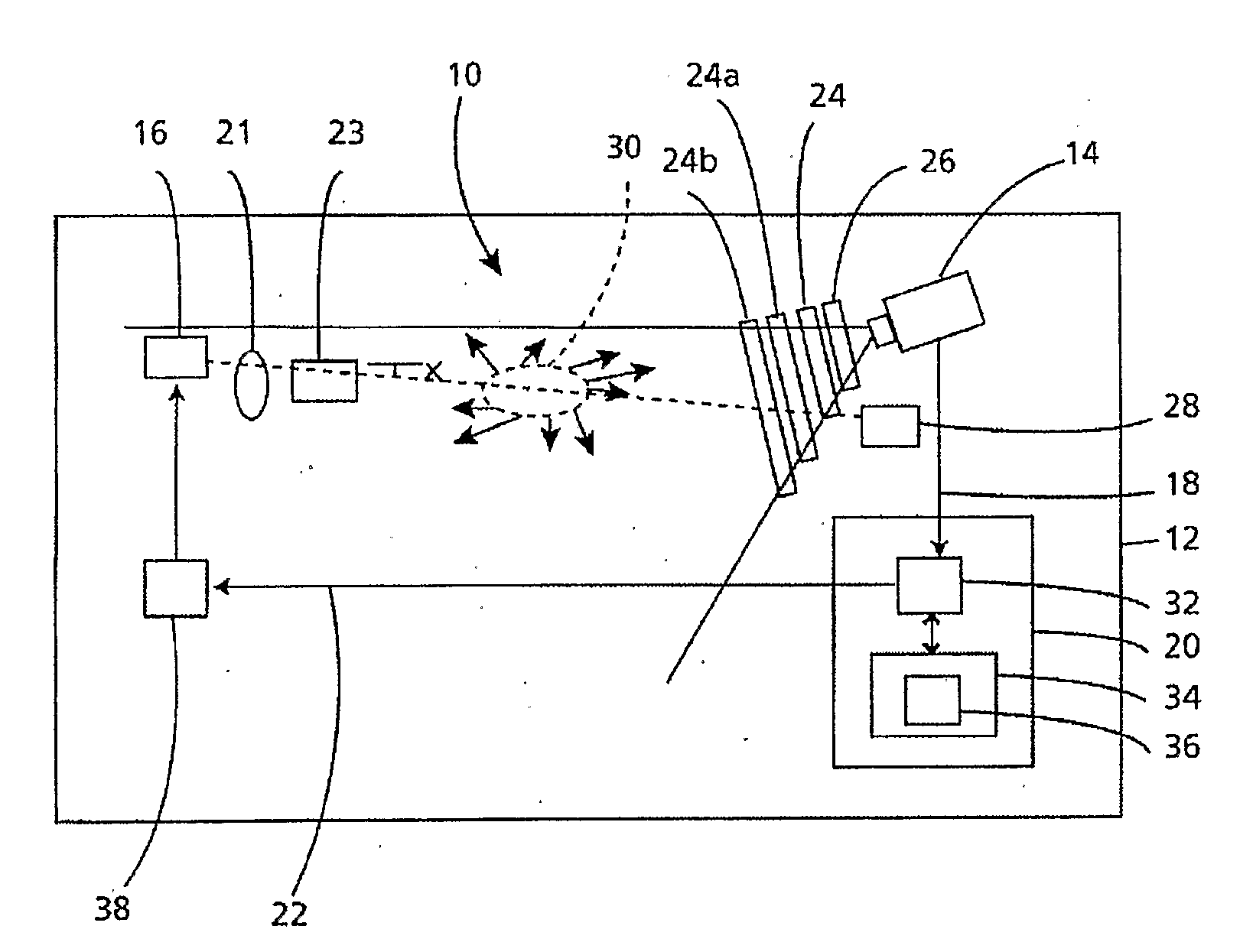
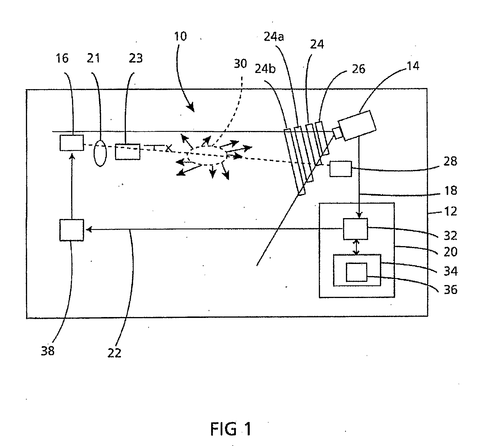
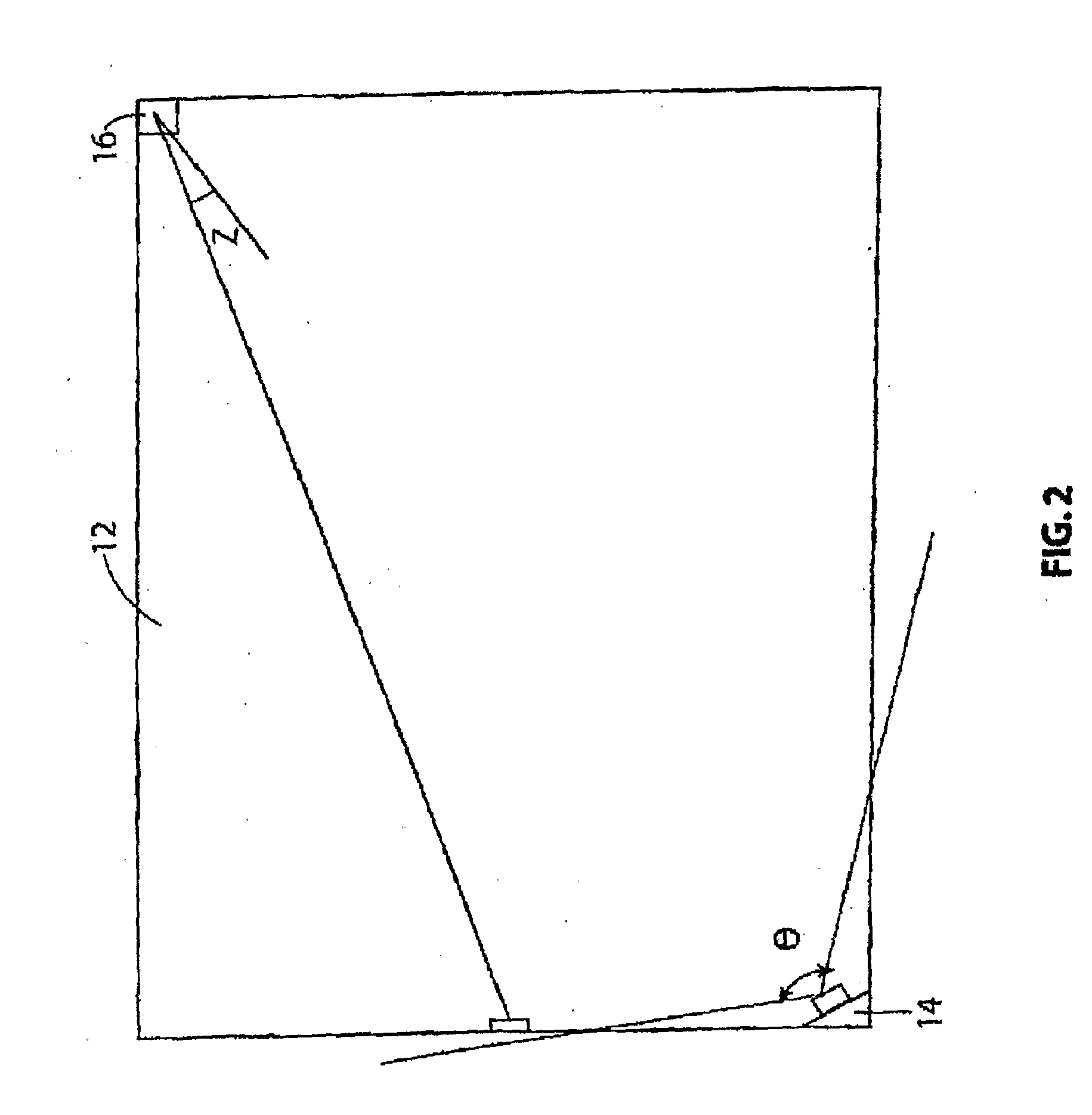
[0140]In preferred embodiments of the invention, there is provided a method and apparatus for detecting particles comprising emoting a beam of radiation into a monitored region and detecting a variation in images of the region indicating the presence of the particles. More particularly, embodiments of the present invention provide an indication of the location of the particles. In essence, embodiments of the present invention provide a particle detection system, which provides for addressability of detected particles, namely, their location by direct detection without the need for sampling the monitored environment or having to place a detector(s) in a useful location within the environment for particle detection. The beam of radiation may comprise one or more light beams emitted from one or more light source(s) and, variation of images of the monitored region or zone may be detected by one or more image capture devices such as cameras.

[0141]In further preferred embodiments of the p...


PUM


Abstract

The invention provides use of one or more emitted beams of radiation (16), for example, laser beam(s), in combination with an image capturing means (14), for example, one or more video cameras and / or optical elements to detect particles (30), for example smoke particles, located in an open space (12).

Description

RELATED APPLICATIONS[0001]This application claims priority to Australian Provisional Patent Application No. 2004906488, filed 12 Nov. 2004 and entitled “Particle Detector, System and Method” and, the specification thereof. Is incorporated herein by reference in its entirety and for all purposes.FIELD OF INVENTION[0002]The present invention relates to an improved sensor apparatus and improved method of sensing. In particular the present invention relates to an improved particle detector and method of detecting particles. It will be convenient to hereinafter describe the invention in relation to the use of one or more emitted beams of radiation, for example, laser beam(s), to detect particles located in an open space, however, it should be appreciated that the present invention is not limited to that use, only.BACKGROUND OF THE INVENTION[0003]Throughout this specification the use of the word ‘inventor’ in singular form may be taken as reference to one (singular) or all (plural) invent...

Claims


Application Information

Patent Timeline
Patent Type & Authority Applications(United States)
IPC IPC(8): G08B17/10H04N7/18G01S17/04G01S17/87
CPCG01N21/49G01N21/532G01S17/026G01S17/87G01S17/95G08B17/107G08B29/043G08B29/24G08B25/10G08B17/103G01S7/4873G01S7/4876G08B17/125G01S17/04G01N33/0031Y02A90/10G08B17/10G01N21/17G01N2021/1765G01N15/1463G01N2201/06113G08B17/117G08B29/185
Inventor KNOX, RONBOETTGER, KARLAJAY, KEMAL
Owner GARRETT THERMAL SYST LTD
Why Eureka
Try Eureka