
Video projection device

a projection device and video technology, applied in the direction of printers, cameras, instruments, etc., can solve the problems of increasing man-hour and cost, complicated switching operation, and large scale of the mechanism required for maintaining high accuracy, so as to achieve the effect of simple structure and without complicated operation

Active Publication Date: 2008-12-04
KONICA MINOLTA OPTO
View PDF6 Cites 5 Cited by
  • Summary
  • Abstract
  • Description
  • Claims
  • Application Information

AI Technical Summary

Benefits of technology

[0019]In view of the circumstances described above, the present invention has been made, and it is an object of the invention to provide a video projection device capable of preventing a focus position shift accompanying attachment and detachment of a converter lens or aberration deterioration accompanying replacement of a projection lens without complicated operation and complicated structure.

Problems solved by technology

As a result, a mechanism required for maintaining high accuracy becomes large-scaled, increasing man-hour and costs.
However, the focus needs to be adjusted with the focus mechanism of the projection lens every time the converter lens is attached or detached, which complicates switching operation.
However, this requires a plurality of cylindrical lenses, and complicates structure for linear driving in the focus mechanism, thus leading to cost increase.
Moreover, configuration such that one of a plurality of types of projection lenses is replaceably loaded results in aberration deterioration depending on matching between the converter lens and the projection lens.

Method used


Image

  • Video projection device
  • Video projection device
  • Video projection device

Examples


Embodiment Construction

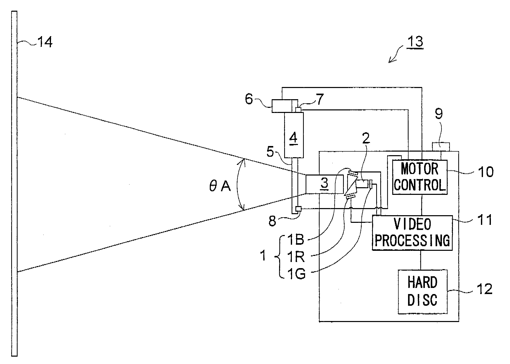
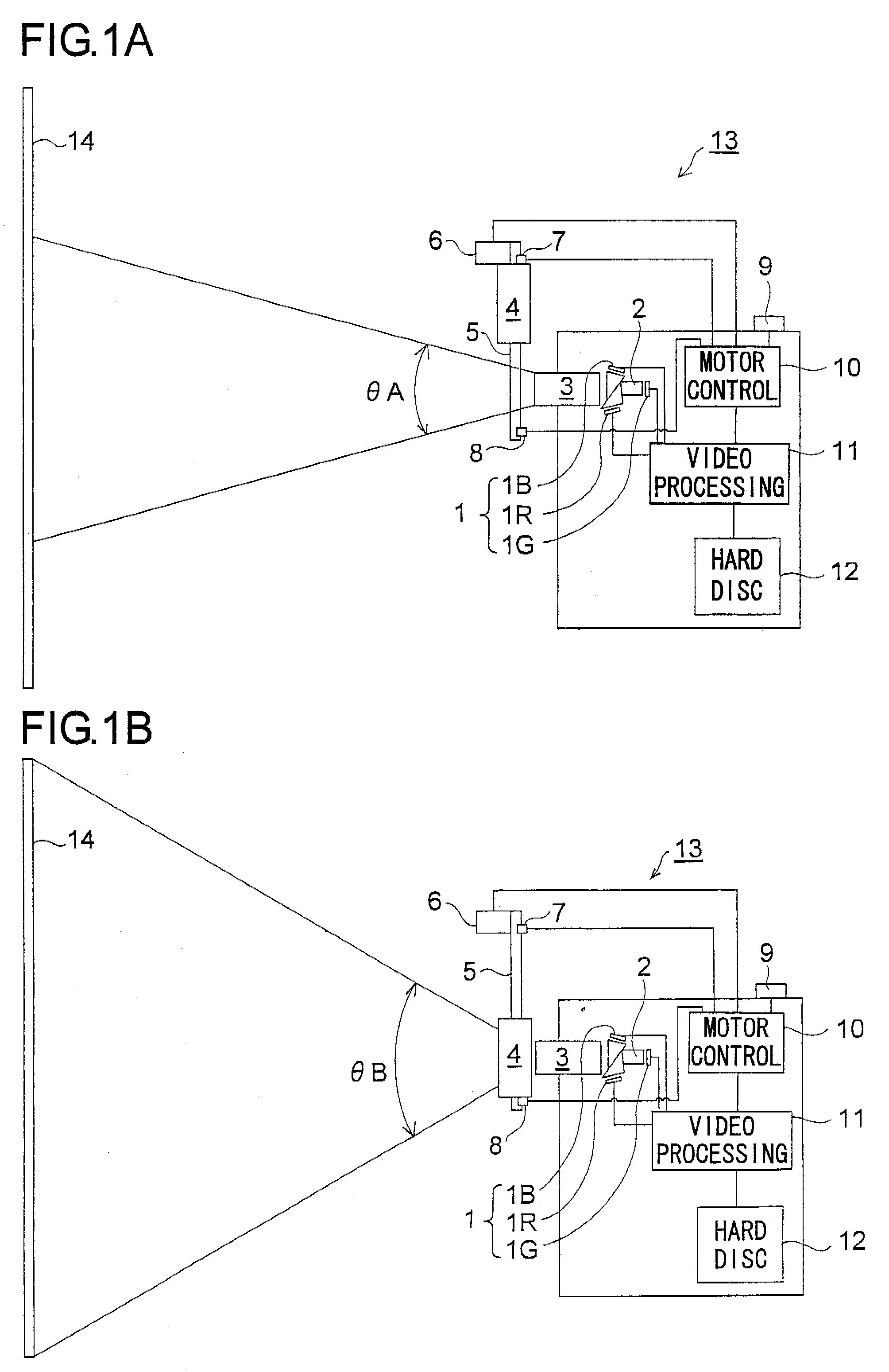
[0035]Hereinafter, embodiments, etc. of a video projection device according to the present invention will be described with reference to the accompanying drawings. FIGS. 1A and 1B show schematic configuration of a video projection device 13 according to one embodiment of the invention. This video projection device 13 projects, on a screen 14 by using a projection lens 3 attachably and detachably provided with a converter lens 4, a video displayed on a video display element 1 by an electrical video signal. FIG. 1A shows a state before the converter lens 4 is attached (non-attached state), and FIG. 1B shows a state after the converter lens 4 is attached (attached state). Here, a projector for digital cinema is assumed as the video projection device 13, but it can also be used for other applications (a projector for home theater, etc.).

[0036]The video projection device 13 has a dichroic prism 2, the projection lens 3, the converter lens 4, etc. in a projection optical system. The video...


PUM


Abstract

A video projection device has one of a plurality of types of projection lenses replaceably loaded and projects a video on a screen at a fixed position. The video projection device includes: a converter lens which is composed of a plurality of lenses, which is afocal as a whole, and which is detachably provided in front of the projection lens to convert projection magnification; and a gap adjustment mechanism changing a predetermined gap in the converter lens to a setting in accordance with at least one of a projection distance to the screen and the type of the projection lens loaded.

Description

[0001]This application is based on Japanese Patent Application No. 2007-142047 filed on May 29, 2007, the contents of which are hereby incorporated by reference.BACKGROUND OF THE INVENTION[0002]1. Field of the Invention[0003]The present invention relates to a video projection device, and more specifically to a video projection device (for example, projector for digital cinema) having a converter lens attachably and detachably provided for a projection lens.[0004]2. Description of Related Art[0005]In a theater, to deal with various image face formats, a converter lens is attached to a projection lens. Converter lenses are not limited to those for projection (for example, for a projector), but those for photographing (for example, for a camera) are conventionally known. Moreover, they are divided into a plurality of types depending on differences in conversion magnification or attachment and detachment position. For example, as types having different conversion magnifications (wide ty...

Claims


Application Information

Patent Timeline
Patent Type & Authority Applications(United States)
IPC IPC(8): G03B21/14
CPCG02B13/16G02B15/06G02B15/10G03B21/14H04N9/317G03B21/142
Inventor MATSUDA, TOKUJISAWAMURA, SHIGERU
Owner KONICA MINOLTA OPTO
Features
  • Generate Ideas
  • Intellectual Property
  • Life Sciences
  • Materials
  • Tech Scout
  • Unparalleled Data Quality
  • Higher Quality Content
  • 60% Fewer Hallucinations
Learn More