Method to make a perpendicular magnetic recording head with a bottom side shield

Active Publication Date: 2008-12-04
HEADWAY TECH INC
View PDF16 Cites 51 Cited by
  • Summary
  • Abstract
  • Description
  • Claims
  • Application Information

AI Technical Summary

Benefits of technology

[0011]A second object of the present invention is to provide a method of forming such a shielded pole structure for a perpendicular magnetic recording head in which side fringing of the magnetic field is significantly reduced, while the recording flux is strong and has a h

Problems solved by technology

A significant problem with magnetic pole structures that are currently used to produce perpendicular fields, is that the fields tend to exhibit significant lateral fringing, thereby producing unwanted side-writing (writing in adjacent tracks).
This problem is much more evident in the perpendicular writing head than in

Method used


Image

  • Method to make a perpendicular magnetic recording head with a bottom side shield
  • Method to make a perpendicular magnetic recording head with a bottom side shield
  • Method to make a perpendicular magnetic recording head with a bottom side shield

Examples


Embodiment Construction

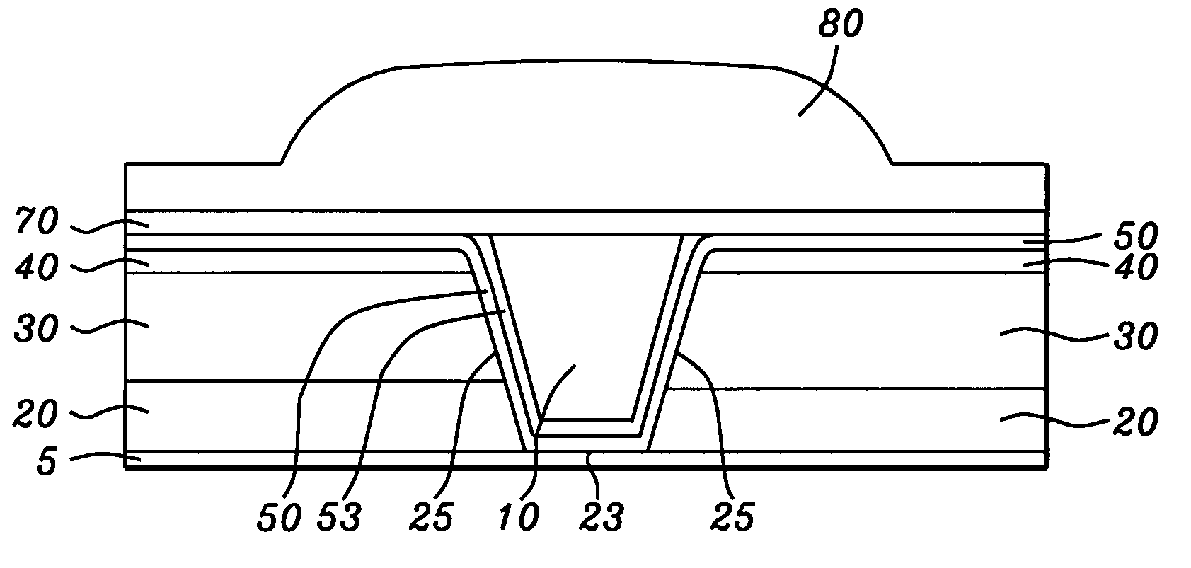
[0022]The preferred embodiment of the present invention is a shielded pole structure for use within a perpendicular magnetic recording (PMR) head, in which the pole tip is formed and shaped within a trench formed between a pair non-magnetic layers and a pair of bottom side shields and is thereafter covered from above by a write-gap layer and an upper shield. This three-way shield formation (two bottom side shields, one upper shield) effectively eliminates side writing by the pole while maintaining flux strength and flux definition and, thereby, allows the formation of a physically larger pole while still maintaining desired track width definition.

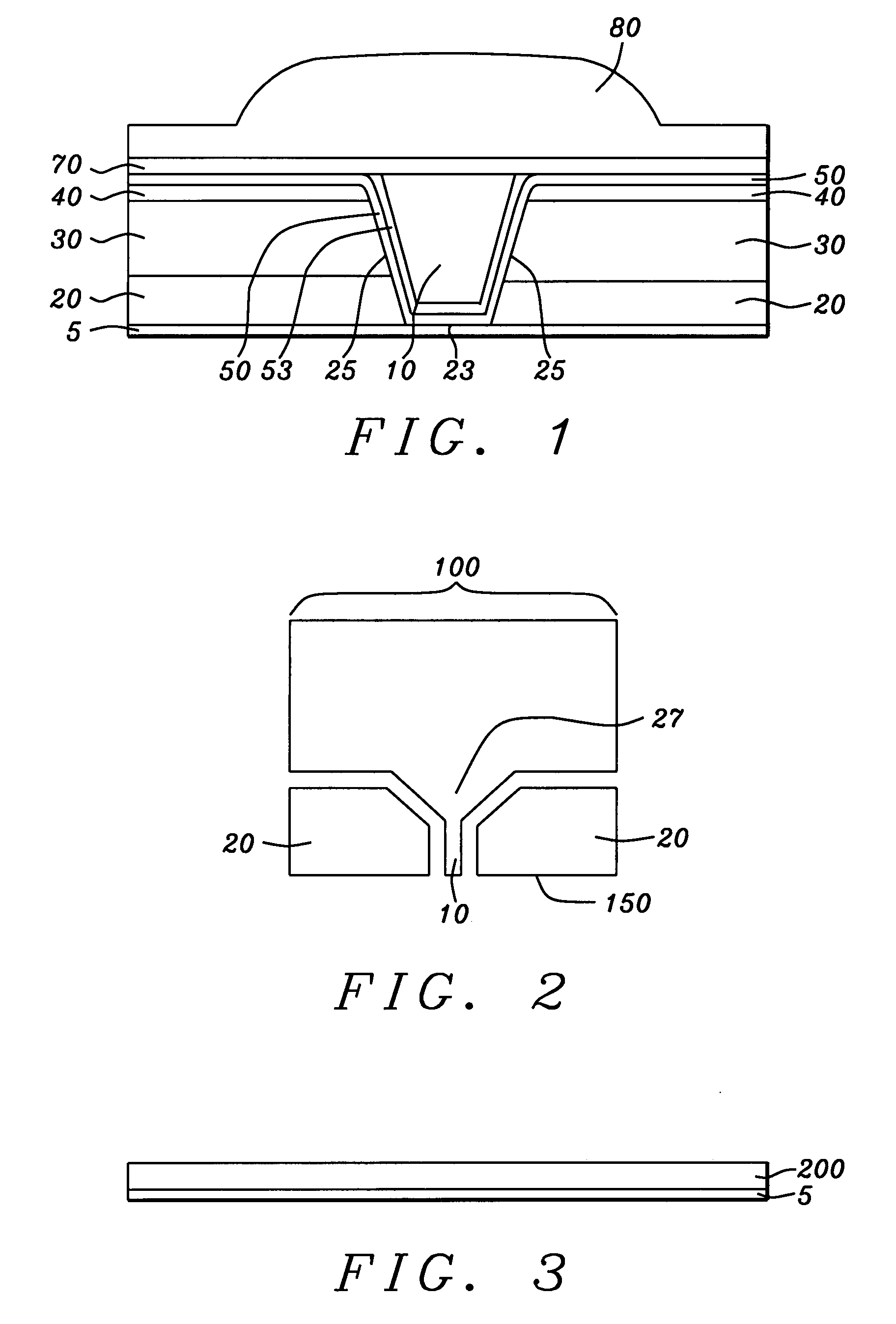
[0023]Two views, front and overhead, of the completed pole fabrication can be seen by referring to FIGS. 1 and 2. FIG. 1 is a schematic view facing the ABS plane of the shielded PMR pole structure as it appears when formed as part of the PMR head (nominally called the “front” of the head). This view shows, in a vertical cross-section, a sub...


PUM

PropertyMeasurementUnit
Poweraaaaaaaaaa
Poweraaaaaaaaaa
Volumetric flow rateaaaaaaaaaa

Abstract

A perpendicular magnetic recording (PMR) head is fabricated with a pole tip shielded laterally by a separated pair of bottom side shields and shielded from above by an upper shield. The bottom side shields surround a lower portion of the pole tip while the upper portion of the pole tip is surrounded by non-magnetic layers. The bottom shields and the non-magnetic layer form wedge-shaped trench in which the pole tip is formed by a self-aligned plating process. The wedge shape is formed by a RIE process using specific gases applied through a masking layer formed of material that has a slower etch rate than the non-magnetic material or the shield material. A masking layer of Ta, Ru/Ta, TaN or Ti, formed on a non-magnetic layer of alumina that is formed on a shield layer of NiFe and using RIE gases of CH3OH, CO or NH3 or their combinations, produces the desired result. A write gap layer and an upper shield is then formed above the side shields and pole. The resulting structure substantially eliminates track overwrite while maintaining good track definition.

Description

[0001]This application is Related to Docket Number HT 05-039, Ser. No. 11 / 345,892, Filing Date Feb. 2, 2006, Assigned to the Same Assignee as the Present Application and herein incorporated by reference in its entirety.BACKGROUND OF THE INVENTION[0002]1. Field of the Invention[0003]This invention relates generally to magnetic recording heads, particularly to perpendicular recording heads that produce their recording magnetic fields perpendicularly to the recording medium[0004]2. Description of the Related Art[0005]The increasing need for high recording area densities (up to 500 Gb / in2) is making the perpendicular magnetic recording head (PMR head) a replacement of choice for the longitudinal magnetic recording head (LMR head).[0006]By means of fringing magnetic fields that extend between two emerging pole pieces, longitudinal recording heads form small magnetic domains within the surface plane of the magnetic medium (hard disk). As recorded area densities increase, these domains mus...

Claims


Application Information

Patent Timeline
IPC IPC(8): G11B5/127G11B5/147H04R31/00
CPCG11B5/1278G11B5/3116Y10T29/49052G11B5/3163Y10T29/49032G11B5/315
Inventor HAN, CHERNG-CHYILI, MINLIU, FENGLINGUAN, LIJIE
Owner HEADWAY TECH INC
Why Eureka
Try Eureka