Vehicular headlamp

a headlamp and headlamp technology, applied in the field of headlamps, can solve the problems of insufficient illumination of the host vehicle lane, inability to correct for the maximum light intensity area, and the risk of dazzling the preceding vehicle, so as to improve the visibility

Inactive Publication Date: 2008-12-04
KOITO MFG CO LTD
View PDF13 Cites 23 Cited by
  • Summary
  • Abstract
  • Description
  • Claims
  • Application Information

AI Technical Summary

Benefits of technology

[0010]According to one or more embodiments of the present invention, if there is no oncoming vehicle, an illumination direction is deflected toward an oncoming vehicle side. Thus, a maximum light intensity area normally oriented more toward a road shoulder side than a host vehicle lane, i.e., toward a side opposite the oncoming vehicle line, can be oriented toward a linear travel direction of the host vehicle lane. Accordingly the host vehicle lane is brightly illuminated and visibility improved.

Problems solved by technology

However, when the illumination direction is deflected upward, the rearview mirror of the preceding vehicle is illuminated and there is a risk of dazzling the preceding vehicle.
Therefore, even if the illumination direction is deflected upward, it is impossible to correct for the maximum light intensity area being in a direction that deviates from the host vehicle lane.
As a consequence, the illumination of the host vehicle lane is not always sufficient.
Accordingly, the driver may switch to the high-beam distribution pattern by manual operation when there are no oncoming vehicles, but this operation is tiresome.
In cases where there are no oncoming cars and only a preceding vehicle is present, driving using the high-beam distribution pattern requires caution due to the risk of dazzling the preceding vehicle.
Therefore, the illumination of the host vehicle lane where the host vehicle is traveling becomes insufficient and results in inadequate visibility of the host vehicle lane, which is not desirable in terms of driving safety.

Method used


Image

  • Vehicular headlamp
  • Vehicular headlamp
  • Vehicular headlamp

Examples


first embodiment

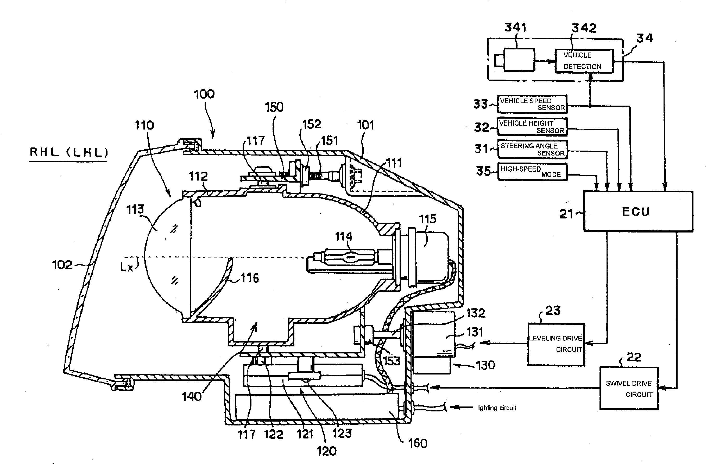
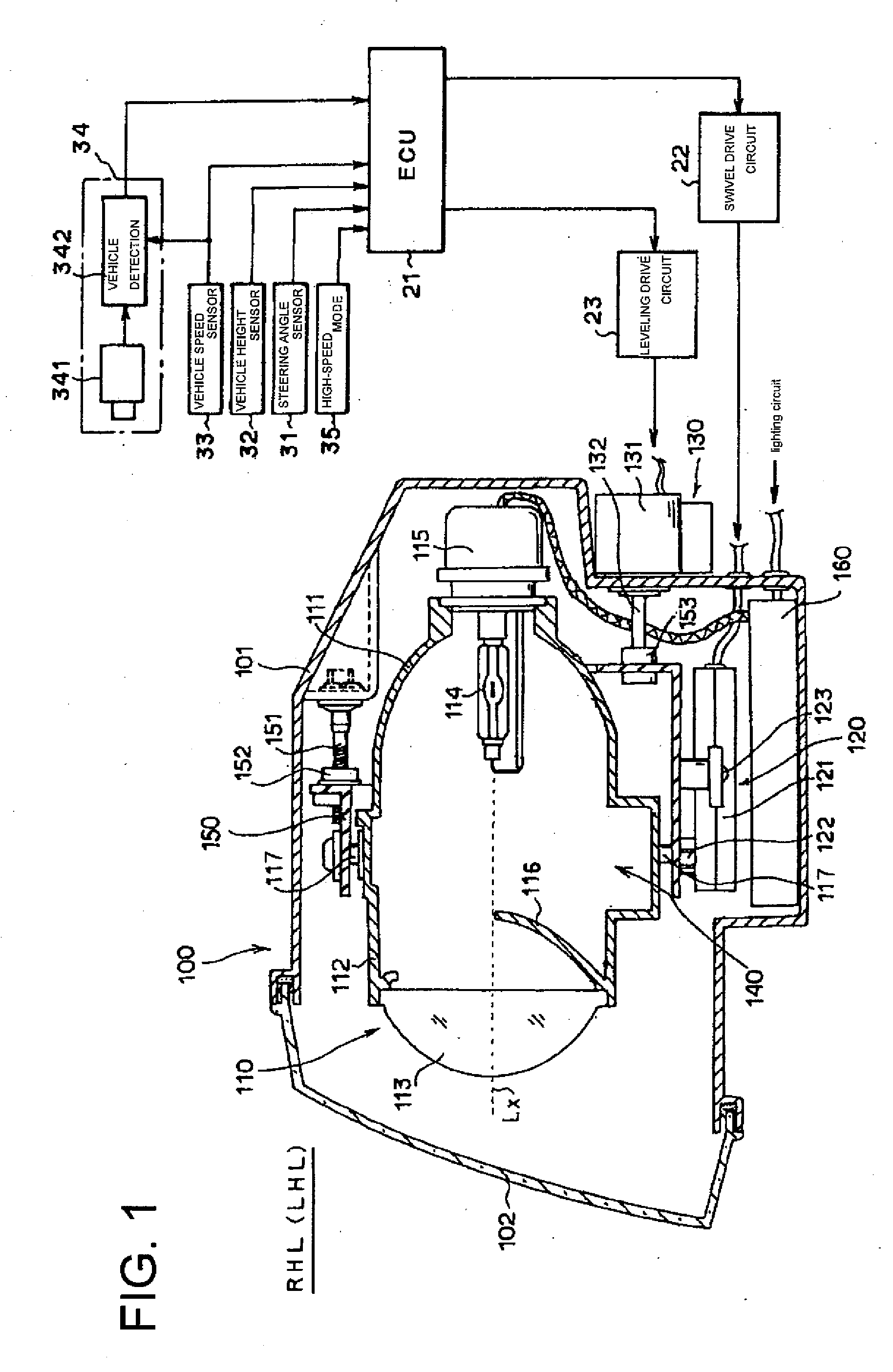
[0023]A first embodiment of the present invention will be described with reference to the accompanying drawings. FIG. 1 is a cross-sectional view of the first embodiment, which can be applied to a right or left headlamp HL of an automobile. Right and left headlamps basically have the same structure, and a right-side headlamp RHL is shown here. In the headlamp RHL, a lamp housing 100 is structured from a container-like lamp body 101 whose front surface is open, and a translucent cover 102 through which light can pass that is attached to the front surface opening of the lamp body 101. A projector type lamp unit 110 is installed within the lamp housing 100 in order to radiate a low-beam light distribution. Also installed within the lamp housing 100 is a lamp unit in order to radiate a high-beam light distribution, which is not shown or described here. The lamp unit 110 is structured such that an optical axis (hereinafter referred to as a lamp unit optical axis) Lx of the lamp unit, i.e...

second embodiment

[0039]FIG. 6 is a frontal view showing a schematic structure of a headlamp according to a second embodiment. The second embodiment is applied to a headlamp HL structured from a plurality of lamp units that use a semiconductor light emitting element such as an LED as a light source. A lamp housing 1 of the headlamp RHL is structured from a lamp body 2 and a translucent front cover 3. Arranged within the lamp housing 1 are three lamp units, namely, first to third lamp units LU1, LU2, LU3, for forming a low-beam distribution pattern, and a fourth lamp unit LU4 for forming a high-beam distribution pattern. The three lamp units LU1, LU2, LU3 are all structured as light collecting lamps, but with different degrees of light collection. The first lamp unit LU1 is structured so as to emit light over a relatively wide area, the second lamp unit LU2 is structured so as collect and emit light over a narrower area, and the third lamp unit LU3 is structured so as to emit light in a concentrated m...


PUM


Abstract

A vehicular headlamp includes a light source for illuminating light from the vehicular headlamp in an illumination direction; a swivel mechanism capable of changing the illumination direction horizontally rightward and leftward; a leveling mechanism capable of changing the illumination direction vertically upward and downward; and electronic control unit capable of controlling the swivel mechanism and the leveling mechanism so as to change the illumination direction toward an oncoming vehicle lane side during linear travel of a vehicle. A method of illumination control for a vehicular headlamp includes illuminating light from the vehicular headlamp in an illumination direction; and changing the illumination direction toward an oncoming vehicle lane side during linear travel of a vehicle.

Description

BACKGROUND OF INVENTION[0001]1. Field of the Invention[0002]The present invention relates to a headlamp of a vehicle such as an automobile, and more specifically relates to a vehicular headlamp that increases an illumination effect in front of a traveling host vehicle to help ensure driving safety.[0003]2. Related Art[0004]In order to increase the safety of a traveling host vehicle, it is necessary to brightly illuminate a travel route of the host vehicle (hereinafter also referred to as a host vehicle lane) and improve the visibility of the host vehicle lane. Especially during high speed driving, visibility in the host vehicle lane up to a certain distant area ahead must be increased. In such cases, the illumination from a high-beam distribution pattern, which is capable of illumination over a long distance and has a laterally wide illumination range, is preferred over the illumination from a low-beam distribution pattern. However, a high-beam distribution pattern is prone to dazzl...

Claims


Application Information

Patent Timeline
Patent Type & Authority Applications(United States)
IPC IPC(8): B60Q1/08F21Y101/00
CPCB60Q1/085B60Q2300/112B60Q2300/122B60Q2300/132B60Q2300/21B60Q2300/41B60Q2300/42F21S48/1186F21S41/17
Inventor NAGANAWA, MASAHITOTSUKAMOTO, MICHIO
Owner KOITO MFG CO LTD
Why Eureka
Try Eureka