
Fixing apparatus, image forming apparatus, and heating member

a technology of fixing apparatus and heating member, applied in the field of image, can solve the problems of shortening the warm-up time of the fixing apparatus, affecting the heating effect of the fixing film,

Active Publication Date: 2008-12-04
RICOH KK
View PDF23 Cites 133 Cited by
  • Summary
  • Abstract
  • Description
  • Claims
  • Application Information

AI Technical Summary

Benefits of technology

[0011]The present invention may provide an image forming apparatus, a fixing apparatus and a heating member that substantially obviates one or more of the problems caused by the limitations and disadvantages of the related art.

Problems solved by technology

Although the fixing apparatus of Japanese Laid-Open Patent Application No. 11-2982 may be suitable for realizing faster operations compared to an apparatus using a fixing roller, this fixing apparatus has limits in shortening a warm-up time (time required for reaching a temperature for performing a printing operation) or a first print time (time required for preparing and performing a printing operation starting from receipt of a print request and ending when a printed paper is discharged).
However, because this fixing apparatus locally heats the nipping part of the fixing film only, areas other than the fixing film are not sufficiently heated.
Thus, the rotation of the fixing film causes the fixing film to become coldest at the mouth of the nipping part.
This leads to poor fixing results.
However, there are limits in precisely fabricating such a thin pipe-like heating member by a cutting process.
The heating member having such a decreased rigidity may be deformed by the chucking force applied by a processing machine or bent during a cutting process.
This makes it difficult to fabricate the heating member with a uniform thickness.
Particularly, in a case where an area of the heating member corresponding to the nipping part is formed in a flat shape or a recessed shape for improving the property of separating a recording medium delivered from the nipping part, it is difficult to perform a precise cutting process on the heating member.
This results in an increase of manufacturing costs.
In other words, fabricating a precise inexpensive heating member becomes more difficult as the heating member becomes thinner.

Method used


Image

  • Fixing apparatus, image forming apparatus, and heating member
  • Fixing apparatus, image forming apparatus, and heating member
  • Fixing apparatus, image forming apparatus, and heating member

Examples


first embodiment

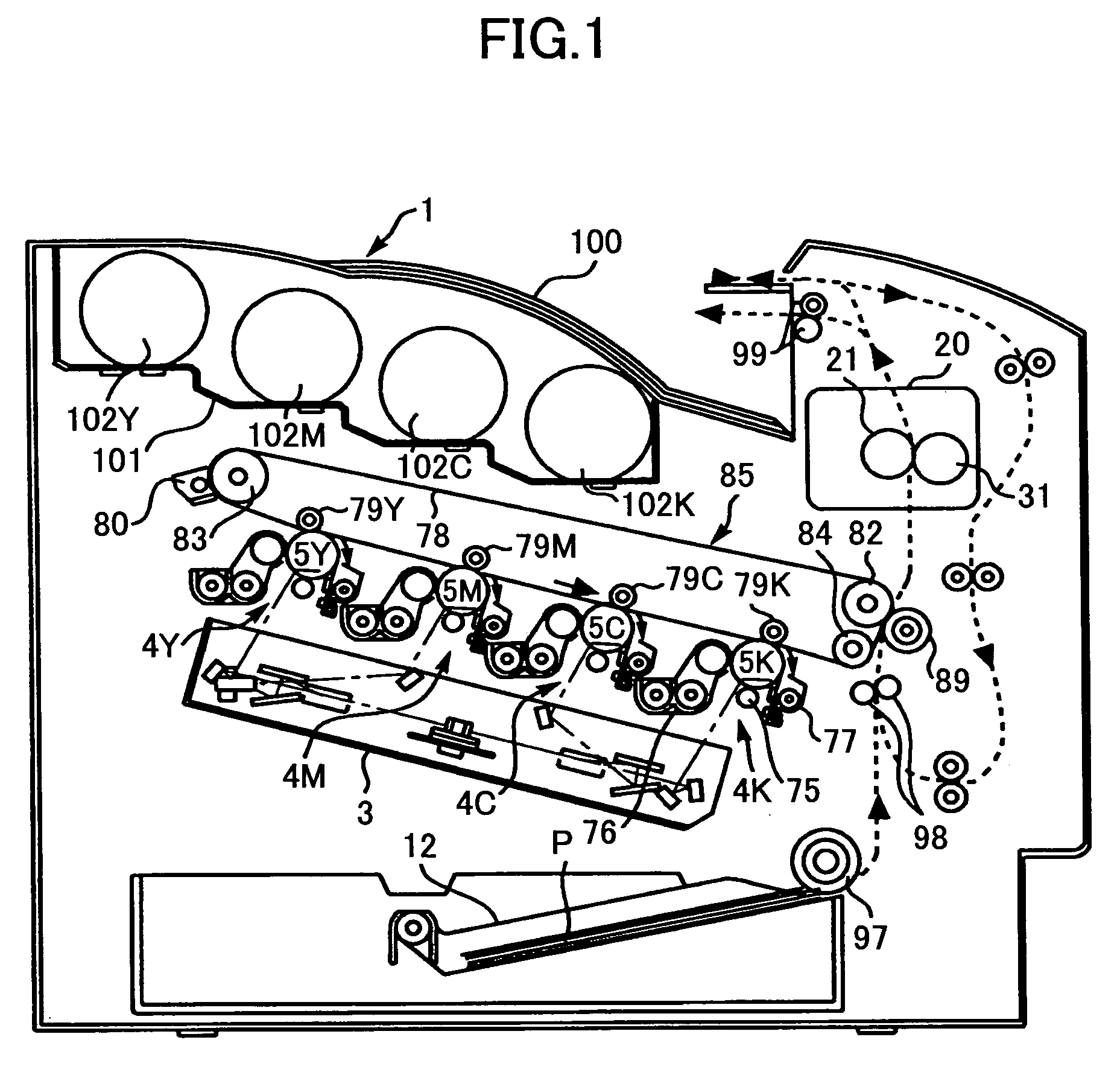
[0030]First, an overall configuration and operation of an image forming apparatus 1 according to an embodiment of the present invention are described with reference to FIG. 1.

[0031]As shown in FIG. 1, the image forming apparatus 1 according to an embodiment of the present invention is a tandem type color printer. Four replaceable toner bottles 102Y, 102M, 102C, and 102K corresponding to the colors of yellow, magenta, cyan, and black are detachably attached to a bottle installing part 101 situated at an upper part of a main body 100 of the image forming apparatus 1.

[0032]An intermediate transfer unit 85 having an intermediate transfer belt 78 is positioned below the bottle installing part 101. Image forming parts 4Y, 4M, 4C, and 4K corresponding to the colors of yellow, magenta, cyan, and black are aligned in a manner facing the intermediate transfer belt 78.

[0033]Each of the image forming parts 4Y, 4M, 4C, and 4K has a corresponding photoconductor drum 5Y, 5M, 5C, and 5K. Each photo...

second embodiment

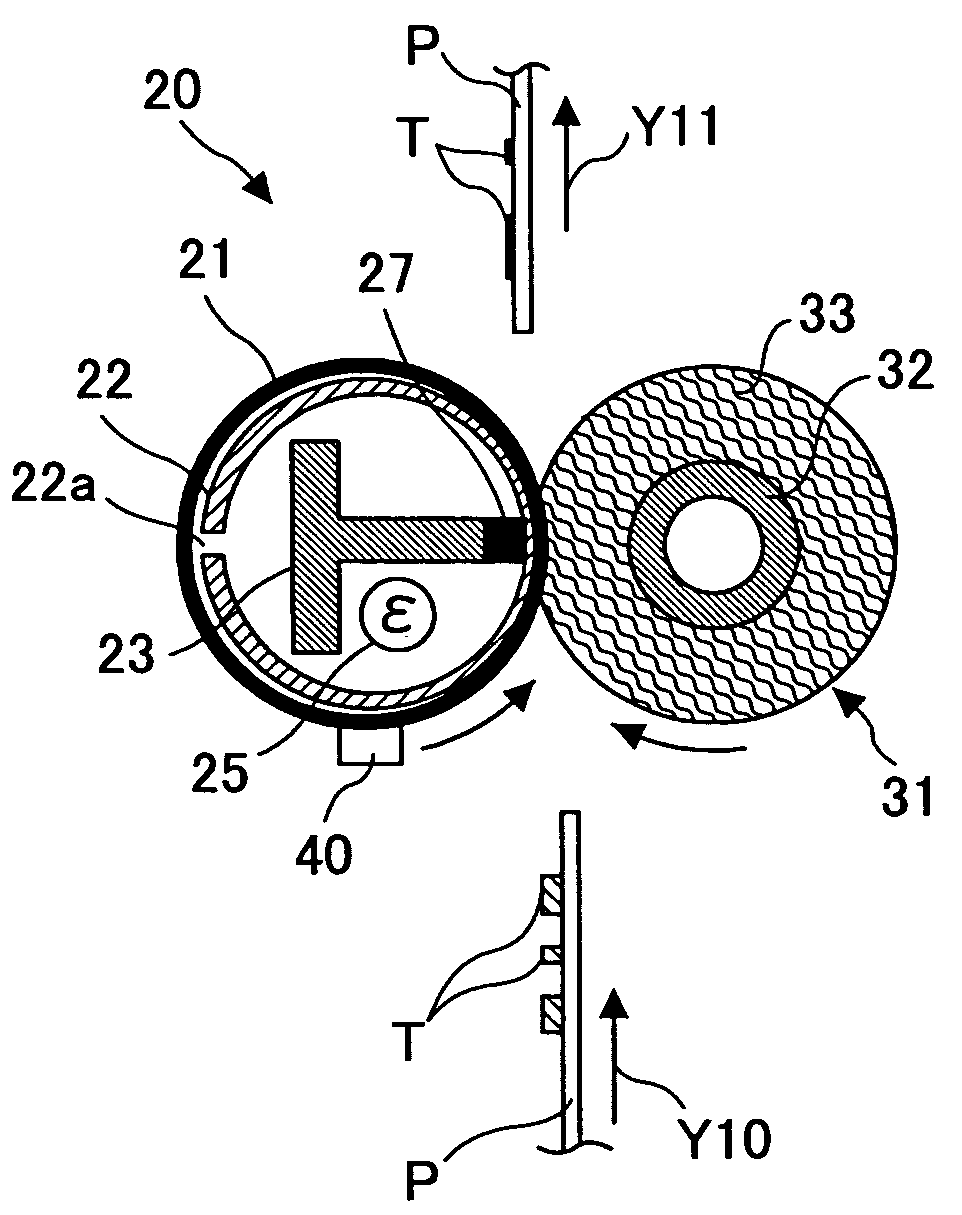
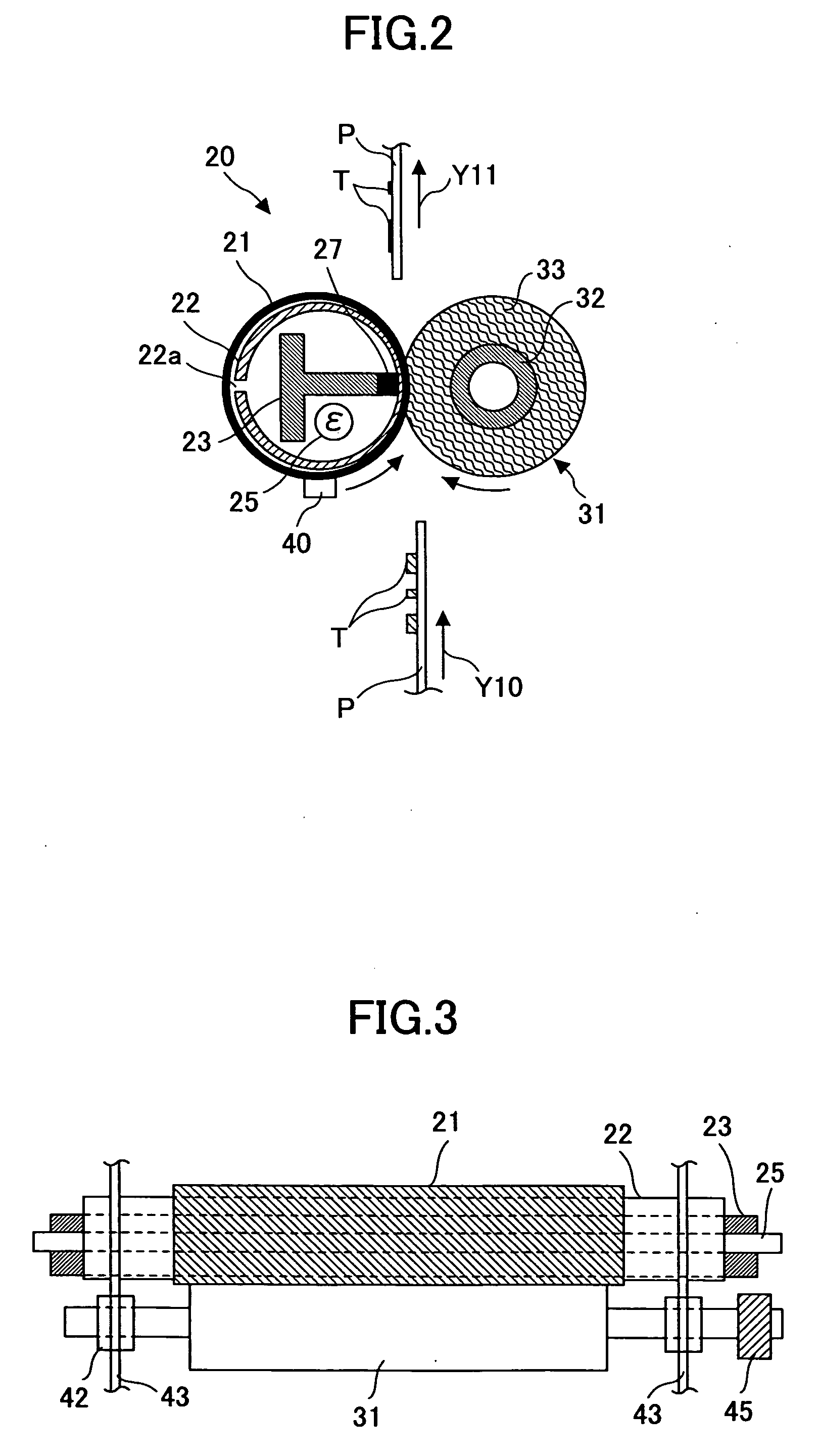
[0102]Next, a fixing apparatus 20A according to a second embodiment of the present invention is described with reference to FIG. 5. FIG. 5 basically corresponds to the configuration shown in FIG. 2. In the second embodiment of the present invention, like components and parts are denoted with like reference numerals as of the first embodiment of the present invention and are not further explained. The fixing apparatus 20A according to the second embodiment of the present invention mainly differs from the fixing apparatus 20 of the first embodiment in that a contacting member 26 serving as the nipping part is provided separately from the heating member 22 and that the nipping part is formed having a recessed shape.

[0103]As shown in FIG. 5, the fixing apparatus 20A according to the second embodiment of the present invention includes, for example, the fixing belt (fixing member) 21, the heating member 22, the reinforcing member 23, the heater (heating source) 25, and the pressure roller...

third embodiment

[0119]Next, a third embodiment of the present invention is described with reference to FIG. 6.

[0120]FIG. 6 is a schematic diagram showing a fixing belt 20B according to a third embodiment of the present invention. FIG. 6 basically corresponds to the configuration shown in FIG. 5. In the third embodiment of the present invention, like components and parts are denoted with like reference numerals as of the first and second embodiments of the present invention and are not further explained. The fixing apparatus 20B according to the third embodiment of the present invention mainly differs from the fixing apparatus 20A of the second embodiment in that the heating member 22 is heated by electromagnetic induction.

[0121]As shown in FIG. 6, the fixing apparatus 20B according to the third embodiment of the present invention includes, for example, the fixing belt (fixing member) 21, the heating member 22, the reinforcing member 23, the pressure roller (pressing member) 31, the contacting membe...


PUM


Abstract

A fixing apparatus includes a flexible endless fixing member that moves in a predetermined direction for heating and melting a toner image, a heating member that is fixed to the fixing member in a position facing at least a part of an inner peripheral surface of the fixing member for heating the fixing member, and a pressing member that provides a nipping part by pressing into contact with the fixing member for conveying a recording medium. The heating member includes a metal plate subjected to a bending process.

Description

BACKGROUND OF THE INVENTION[0001]1. Field of the Invention[0002]The present invention relates to an image forming apparatus (e.g., a copier, a printer, a facsimile machine, a multifunction machine), a fixing apparatus and a heating member that are mounted in the image forming apparatus.[0003]2. Description of the Related Art[0004]Conventionally, there is a known method in which a fixing belt, spanning across plural roller members, is used as a fixing member in an image forming apparatus (e.g., copier, printer) (for example, see Japanese Laid-Open Patent Application No. 11-2982). This type of image forming apparatus includes, for example, a fixing belt (endless belt) used as a fixing member, plural roller members around and between which the fixing belt spans, a heater installed in one of the plural roller members, and a pressure roller (pressing member). The heater heats the fixing belt via its corresponding roller member. Then, a recording medium is conveyed to a nipping part betwe...

Claims


Application Information

Patent Timeline
Patent Type & Authority Applications(United States)
IPC IPC(8): G03G15/20
CPCG03G15/2064G03G2215/2035
Inventor SHINSHI, AKIRA
Owner RICOH KK
Features
  • Generate Ideas
  • Intellectual Property
  • Life Sciences
  • Materials
  • Tech Scout
  • Unparalleled Data Quality
  • Higher Quality Content
  • 60% Fewer Hallucinations
Learn More