Multi-Piston Pump

a multi-piston pump and pump body technology, applied in the direction of machines/engines, braking systems, positive displacement liquid engines, etc., can solve the problems of non-uniform mechanical forces on the bearing of the motor, high production effort and expense of such a multi-piston pump

Inactive Publication Date: 2008-12-04
ROBERT BOSCH GMBH
View PDF6 Cites 71 Cited by
  • Summary
  • Abstract
  • Description
  • Claims
  • Application Information

AI Technical Summary

Problems solved by technology

However, it has been proved in this respect that on the one hand the production effort and expense for such a multi-piston pump are quite high, since many low- and high-pressure lines have to be accommodated in the same housing.
Moreover, the disposition of the piston pumps leads to non-uniform mechanical ...

Method used


Image

  • Multi-Piston Pump
  • Multi-Piston Pump
  • Multi-Piston Pump

Examples


Embodiment Construction

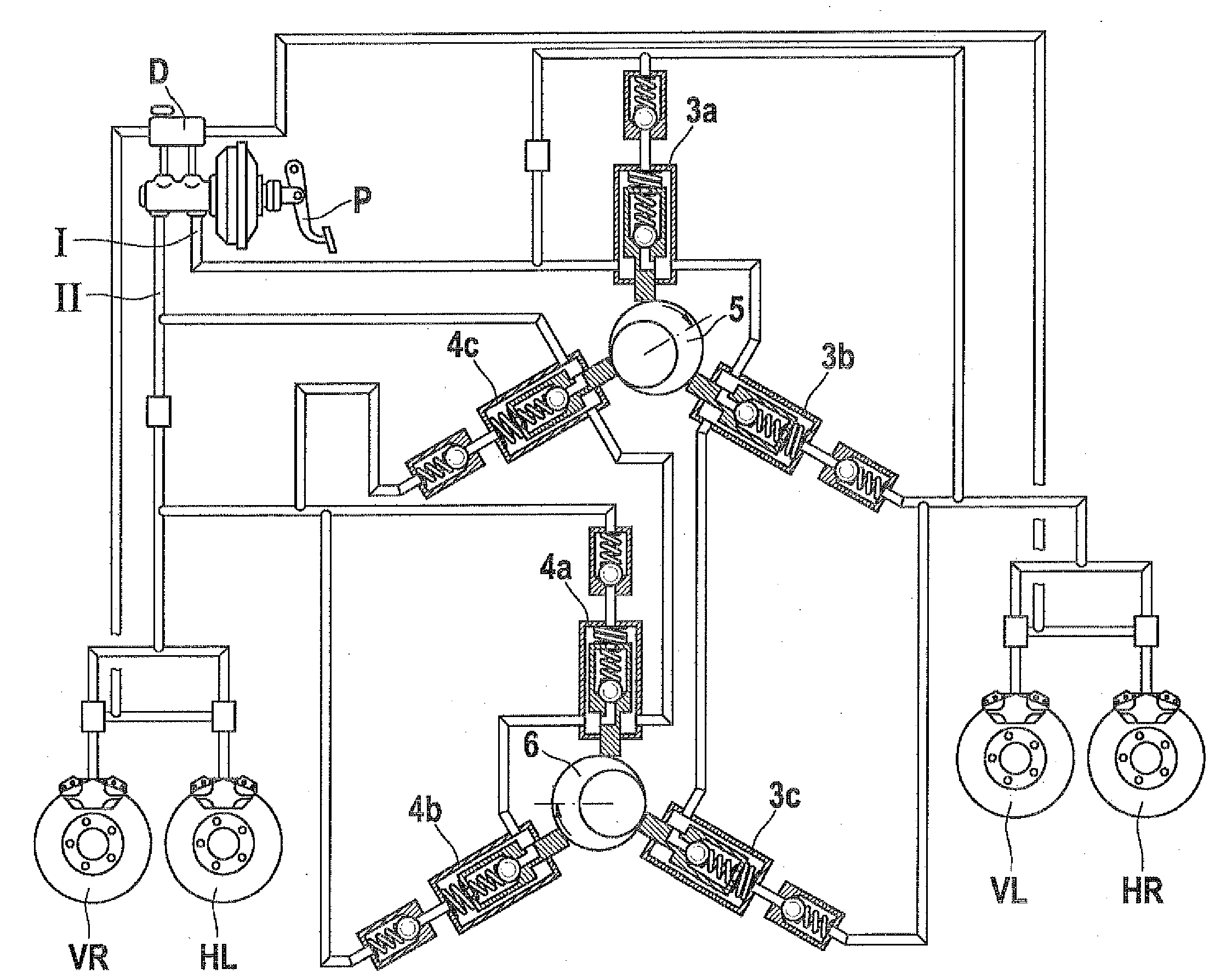
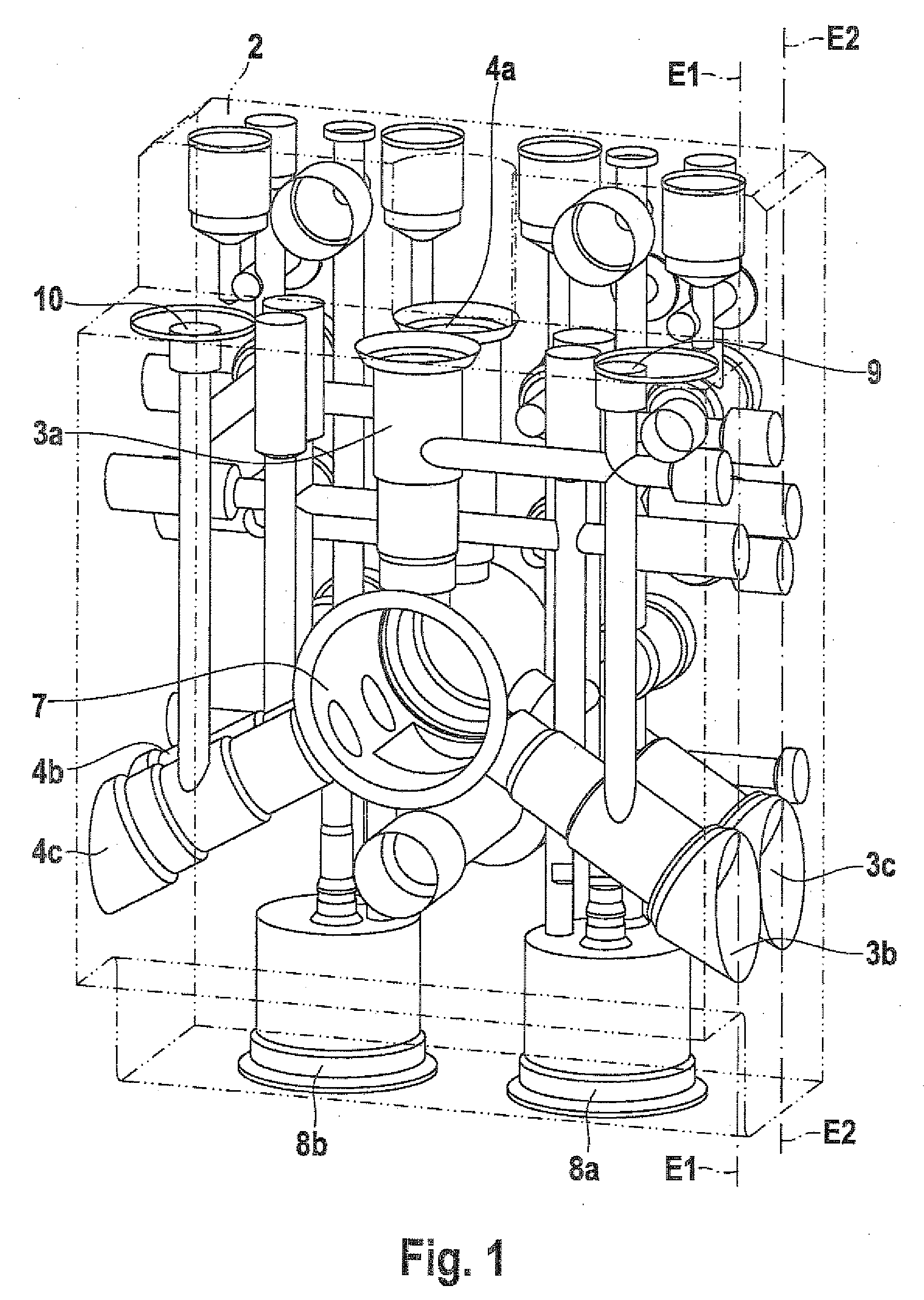
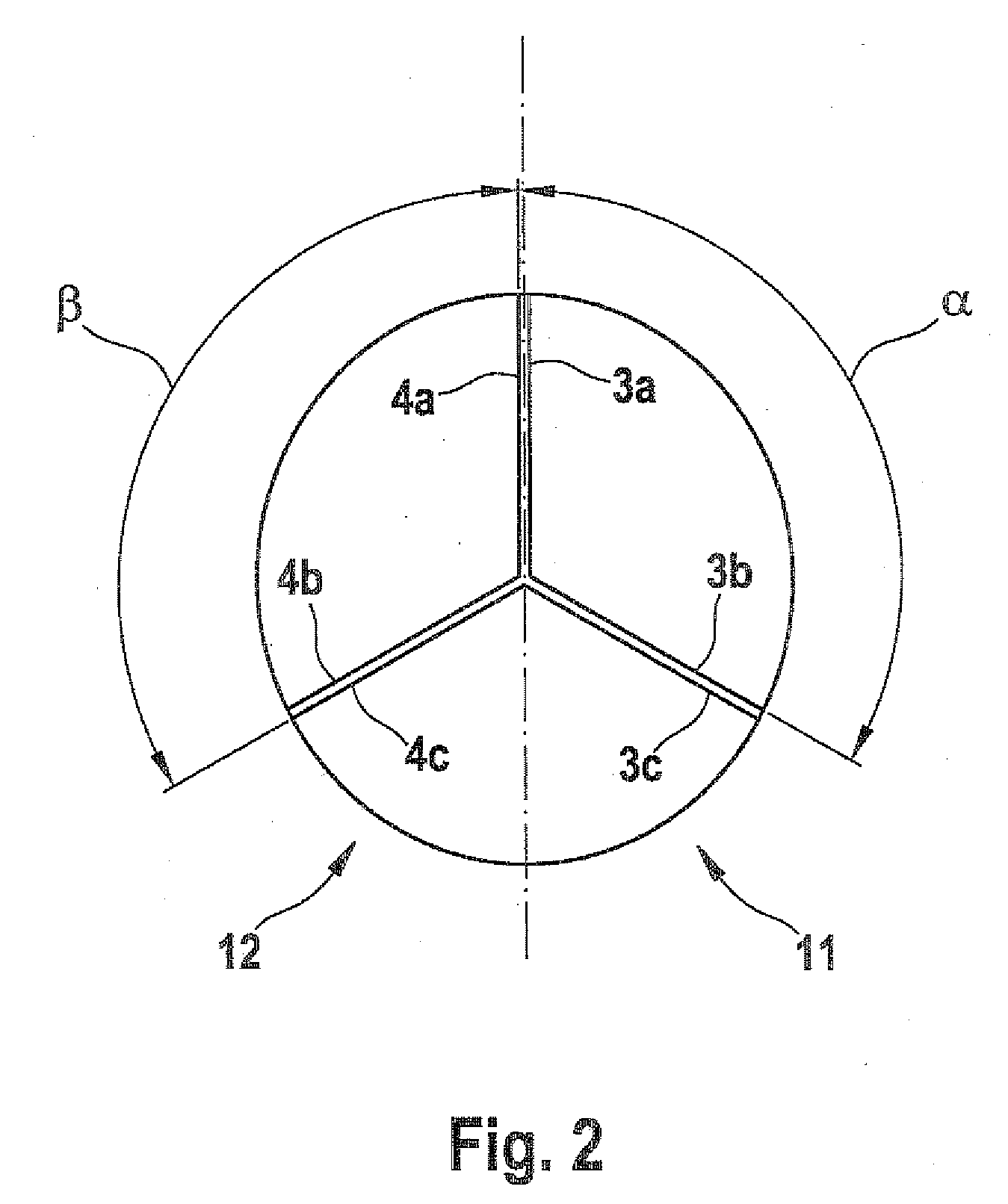
[0014]A multi-piston pump 1 in an exemplary embodiment of the invention will be described below, referring to FIGS. 1 through 3.

[0015]The multi-piston pump 1 includes a housing 2, a first pump unit 3, and a second pump unit 4. The first pump unit 3 includes three piston pumps 3a, 3b, 3c, and the second pump unit 4 includes three piston pumps 4a, 4b, 4c. As can be seen particularly in FIG. 3, three piston pumps each are disposed around a first eccentric 5 and around a second eccentric 6. Two piston pumps 3a, 3b of the first pump unit 3 and one piston pump 4c of the second pump unit 4 are associated with the first eccentric 5. One piston pump 3c of the first pump unit 3 and two piston pumps 4a, 4b of the second pump unit 4 are associated with the second eccentric 6. The piston pumps 3a, 3b, 3c of the first pump unit 3 finish the pressure in a first brake circuit I, and the piston pumps 4a, 4b, 4c of the second pump unit 4 furnish the pressure for a second brake circuit II. Also shown ...


PUM


Abstract

The present invention relates to a multi-piston pump comprising a housing, a first pump unit having a plurality of piston pumps for the pressure supply of a first pressure circuit, a second pump unit having a plurality of piston pumps for the pressure supply of a second pressure circuit, a drive and an eccentric unit having a first eccentric and a second eccentric, wherein the first and the second eccentrics drive the plurality of piston pumps, and wherein the first and second pump units comprise in each case at least one piston pump which can be driven by the first eccentric and one piston pump which can be driven by the second eccentric. In that in each case, one piston pump which is driven by the first eccentric is arranged parallel to a piston pump which is driven by the second eccentric.

Description

PRIOR ARTDisclosure of the Invention[0001]The present invention relates to a multi-piston pump as generically defined by the preamble to claim 1.[0002]One such multi-piston pump is known for instance from German Patent Disclosure DE 101 53 834 A1. Such multi-piston pumps are used in motor vehicles, for instance, for building up the pressure in brake systems. The known multi-piston pump has two eccentrics, which are located in series and each drive three piston pumps. The piston pumps are disposed in two parallel planes at the level of the eccentrics. The piston pumps, each associated with an eccentric, are disposed at different angles to one another around the eccentric. To avoid pressure pulsations, two piston pumps of the first eccentric are connected to a piston pump of the second eccentric, and two piston pumps of the second eccentric are connected to a piston pump of the first eccentric. The eccentrics are disposed rotated by an angle of approximately 150° to one another. Howev...

Claims


Application Information

Patent Timeline
IPC IPC(8): F04B1/04
CPCB60T8/368F04B1/0421F04B1/0538
Inventor PABST, CARSTENGRESCHUCHNA, MARCEL MUNOZDOBERSCHUETZ, CHRISTIAN
Owner ROBERT BOSCH GMBH
Why Eureka
Try Eureka