Coin hopper

a coin hopper and coin technology, applied in the field of coin hoppers, can solve the problems of coin hoppers and wipers that may interfere, coin hoppers that cannot be installed in game machines, and cannot be applied immediately,

Active Publication Date: 2008-12-04
ASAHI SEIKO CO LTD
View PDF3 Cites 6 Cited by
  • Summary
  • Abstract
  • Description
  • Claims
  • Application Information

AI Technical Summary

Benefits of technology

[0014]A first feature of the present invention is to provide a coin hopper capable of discharging coins having different diameters with no trouble even when a coin discharging speed is increased. A second feature of the present invention is to provide a coin hopper that does not pinch coins even when a rotating disk for discharging coins is rotated reversely. A third feature of the present invention is to provide a coin hopper that enables a coin discharging speed to increase and a rotating disk for discharging coins to rotate reversely. A fourth feature of the present invention is to provide a coin hopper that ensures separation of coins one by one and feeding thereof using a rotating disk. A fifth feature of the present invention is to provide a coin hopper capable of detecting rotation of a rotating disk using a simple device.

Problems solved by technology

Conversely, when the coin stoppers are formed low so as to pass below the wiper, the coin stoppers and the wiper may interfere, in a case such as where the wiper is bent when a coin is placed thereon.
Thus, the coin hopper has a limitation in installation in game machines, and thus cannot be applied immediately.
When the coin stopper is continuously held in the retracted position, the coin stopper cannot stop coins, thus coins may not be discharged evenly.
Thus, the technology cannot be applied immediately.
In addition, when the rotating disk is not rotated because a coin is pinched even though a driving voltage is applied to an electric motor for driving the rotating disk, the electric motor may be overheated, thus leading to fire.

Method used


Image

  • Coin hopper
  • Coin hopper
  • Coin hopper

Examples


first embodiment

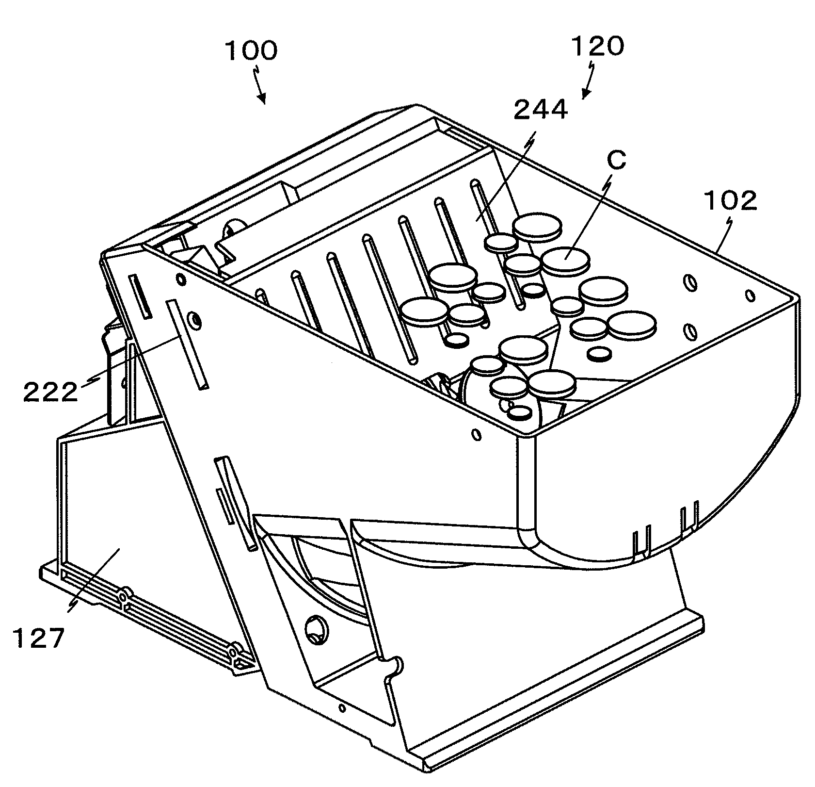
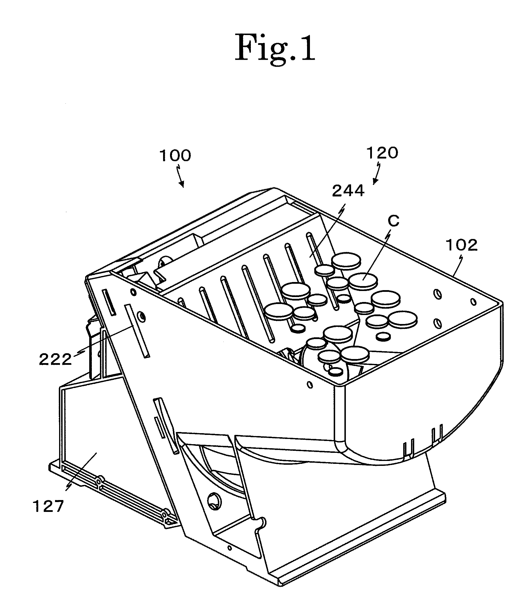
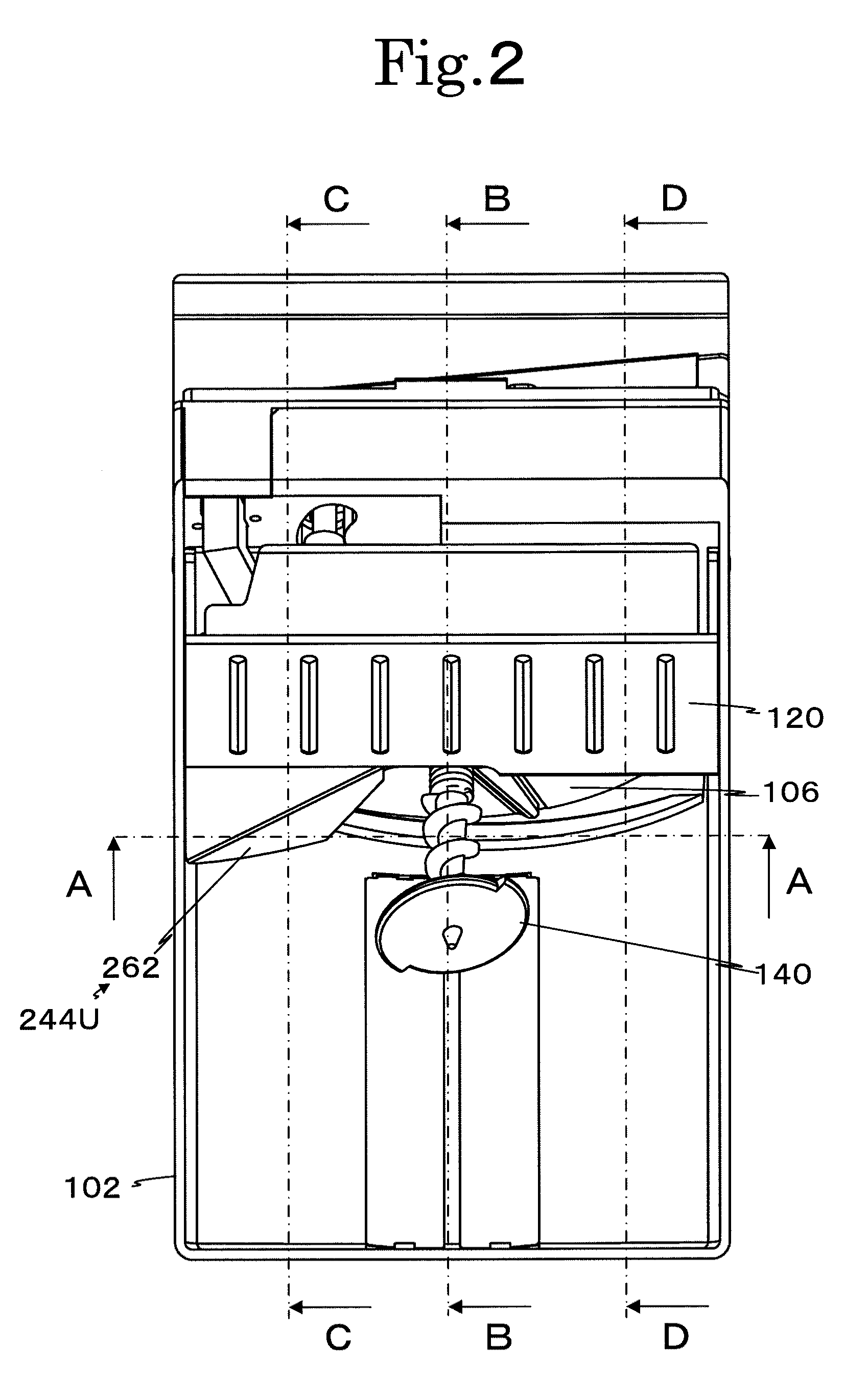
[0067]As shown in FIGS. 1, 4, 5, and 10, a coin hopper 100 includes a holding bowl 102, which holds numerous coins in bulk; an attachment base 104 (see FIG. 10), which supports and fixes the holding bowl 102 obliquely upward; a rotating disk 106, which sorts coins C one by one; a driver 108 of the rotating disk 106; a receiver 112 of coins C; a hopper 114 of coins C; a detector 116 of coins C; and a dropper 118 of coins C according to the present invention; and a regulator 120 of coins C.

[0068]The holding bowl 102 is first explained mainly with reference to FIGS. 1 and 5. The holding bowl 102 holds numerous coins in bulk and feeds the coins toward the rotating disk 106. The holding bowl 102 projects forward (left in FIG. 5) from the attachment base 104, and has a deeper depth toward the rotating disk 106. More specifically, the holding bowl 102 includes a head portion 102A, a coin inlet port 102B, and an outer covering unit 102C. The head portion 102A includes a bottom wall 122 prov...

second embodiment

[0096]Components identical to those in the First Embodiment are provided with identical numeral references. Structures different from those in the First Embodiment are explained below.

[0097]It is preferable that a pressing edge 138 of a coin stopper 128 have a height from a holding surface 134 lower than a thickness of a thinnest coin C. Thereby, even when the thinnest coin C is used, only a coin C whose surface contacts the holding surface 134 is pushed by the pressing edge 138 (coin stopper 128). The structure is preferable in order to prevent two thinnest coins from being pushed by the pressing edge 138 when the coins overlap. However, the pressing edge 138 may have a height higher than the thickness of the thinnest coin. Since a supporting rack 136 is lower than the thickness of the thinnest coin, a coin C overlapping a coin C whose surface contacts the holding surface 134 is not supported by the supporting rack 136 and thus drops into a holding bowl 102. The pressing edge 138, ...


PUM


Abstract

A coin hopper includes a rotating disk provided obliquely upward at a predetermined angle; an outer covering unit covering at least a lower outer circumference of the rotating disk; a holding bowl continuing from the outer covering unit and holding coins; a circular supporting rack provided in a central region of an upper surface of the rotating disk; and coin stoppers being provided on the upper surface of the rotating disk and extending radially from the supporting rack in a circumferential direction to a periphery of the rotating disk at an equal interval. Coins are accepted one by one while a surface thereof is contacted with a holding surface of the upper surface of the rotating disk between the coin stoppers, are moved in one direction while a periphery thereof is held by the supporting rack, and are received from the coin stoppers during transportation by a coin receiver.

Description

CROSS-REFERENCE TO RELATED APPLICATIONS[0001]The present application claims priority under 35 U.S.C. §119 of Japanese Application No. 2007-140947 filed on May 28, 2007 and No. 2007-236054 filed on Sep. 12, 2007, the disclosures of which are expressly incorporated by reference herein in their entireties.BACKGROUND OF THE INVENTION[0002]1. Field of the Invention[0003]The present invention relates to a coin hopper that sorts and discharges coins one by one, the coins being held in bulk in a holding bowl. Specifically, the present invention relates to a coin hopper capable of sorting and discharging coins one by one, the coins having different diameters and being held in bulk in a holding bowl. More specifically, the present invention relates to a coin hopper capable of surely feeding out, one by one, coins having different diameters. Coins herein include currencies, medals and tokens for game machines, and the like.[0004]2. Description of Related Art[0005]As a first conventional techno...

Claims


Application Information

Patent Timeline
Patent Type & Authority Applications(United States)
IPC IPC(8): G07D3/06
CPCG07D3/00G07D9/008
Inventor ENOMOTO, MINORU
Owner ASAHI SEIKO CO LTD
Why Eureka
Try Eureka