Supercapacitor

a supercapacitor and capacitor technology, applied in the field of capacitors, can solve the problems of previously known supercapacitors that were limited to operate at low frequencies, and suffer from disadvantages, and achieve the effects of improving the frequency of operation, facilitating ionic transport within the electrode plane, and increasing the frequency of operation

Active Publication Date: 2016-09-15
UNITED STATES OF AMERICA THE AS REPRESENTED BY THE SEC OF THE ARMY
View PDF14 Cites 8 Cited by
  • Summary
  • Abstract
  • Description
  • Claims
  • Application Information

AI Technical Summary

Benefits of technology

[0021]In some embodiments of the invention, nanotubes and / or nanoparticles may be further intermixed with the carbonaceous material. The nanotubes or nanoparticles produce additional space between particles or flakes of the carbonaceous material making ionic transport within the electrode plane easier while the etched holes in the electrodes provide easier ionic transport perpendicular to the electrode plane. This combination, in turn, results in increased frequency of operation as well as increased discharge and charging speed for the supercapacitor by achieving reduced ionic impedance.
[0022]In other embodiments, the electrodes may have a plurality of elongated orifices extending through the carbonaceous material between the metal current collector and separator in a manner similar to holes. In either case, the holes or elongated orifices may be spaced apart no more than about 25.4 microns to create a facilitated pathway for travel of the electrolytic ions during charging and discharging of the capacitor thereby significantly increasing the operational frequency of the capacitor. For example, the holes may have a length / width or diameter of about 10 nm to 100 microns, and the elongated orifices may have a width of about 10 nm to about 100 microns. The size of the holes or elongated orifices and spacing may be judiciously selected so as to remove no more than about 50% of the carbonaceous material of the electrodes. The spacing of the holes or elongated orifices could be less than the thickness of the electrodes. Also, the length / width or diameter of the holes or the width of the elongated orifices may be larger than the interparticle pore size in the electrode material. The holes or elongated orifices can be patterned using a mesh placed on top of the carbonaceous material during their forming process. The electrodes can be created by depositing carbonaceous material on a mesh with the mesh also being used as a template for forming the holes or elongated orifices and / or for patterning the deposition of the carbonaceous material onto the current collectors.

Problems solved by technology

Supercapacitors do, however, suffer from some disadvantages due, in part, to the extended path necessary for the ions to travel during both charge and discharge.
First, the previously known supercapacitors were limited to operate at low frequencies, typically less than 1 Hertz.
Such low frequencies, of course, limit their applications in electrical circuits.
A still further disadvantage of these previously known supercapacitors is that the rate of charging, as well as discharging, is relatively slow.
This relatively slow charging and discharging of the supercapacitor is due primarily to the ionic impedance present in the carbon based electrodes used for the supercapacitor.

Method used


Image

  • Supercapacitor
  • Supercapacitor
  • Supercapacitor

Examples


Embodiment Construction

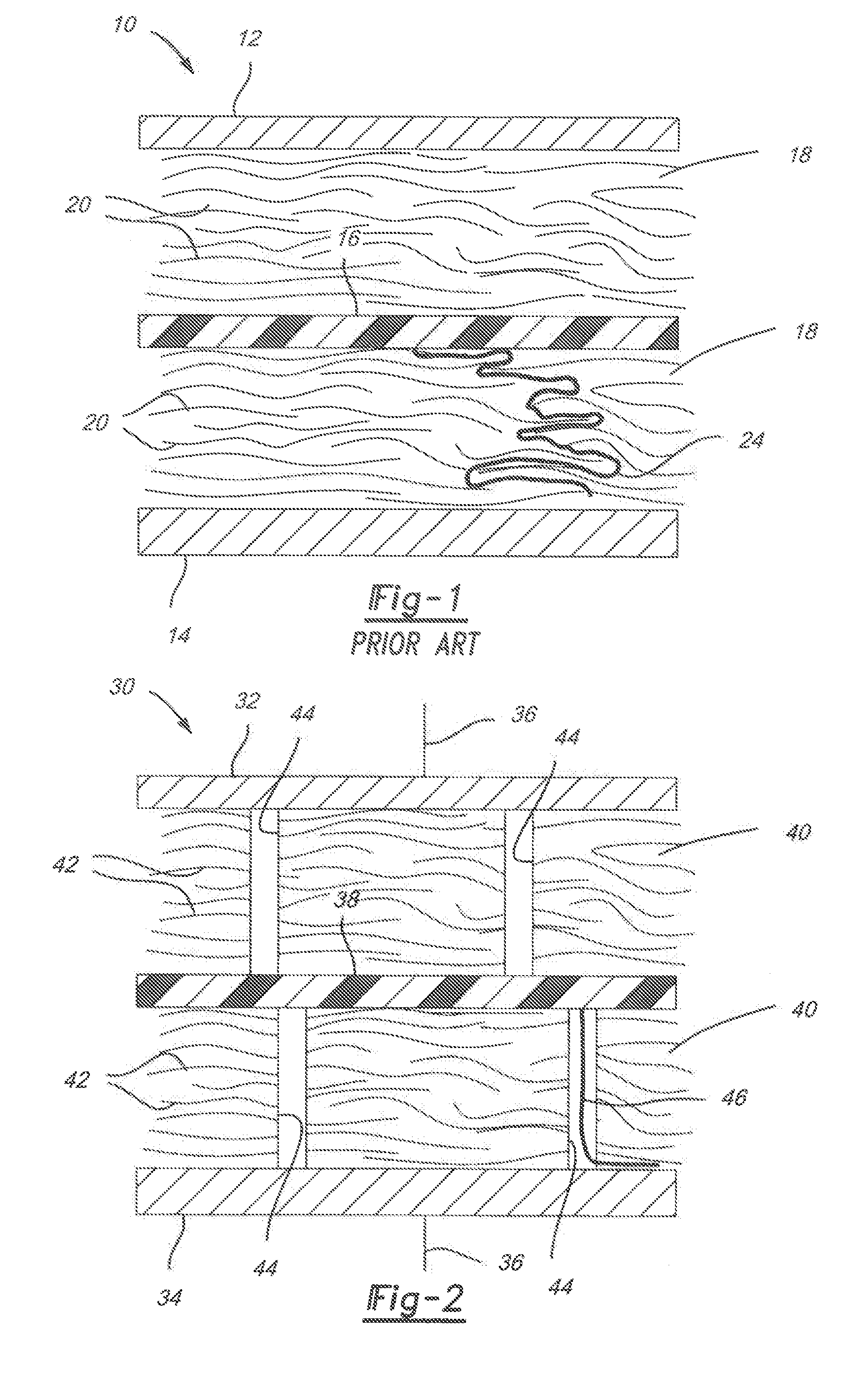
[0036]With reference first to FIG. 2, a first embodiment of a supercapacitor or electrochemical capacitor 30 according to the present invention is shown. Like the previously known supercapacitors of FIG. 1, the supercapacitor 30 generally includes a pair of spaced apart metal current collectors 32 and 34 which are spaced apart by a few microns to a few hundred microns and are parallel to each other. Each current collector 32 and 34 is connected to its associated electrical circuit (not shown) by a lead 36.

[0037]A separator 38 constructed of an electrical insulating material, such as a porous polymer, is positioned in between the metal current collectors 32 and 34 and thus separates a pair of electrodes 40 from each other. Any conventional material may be used for the separator 38. In some embodiments, the separator 38 may be a porous, electrically insulating polymer or paper film which keeps the electrodes 40 from electrically contacting and discharging, while allowing ions to diffu...


PUM


Abstract

A supercapacitor or electrochemical capacitor includes spaced apart electrodes which are separated from each other by a separator made of an electrically insulating material. Each electrode is formed of carbonaceous material and capable of being impregnated with a liquid electrolyte. Metal current collectors are provided on the sides of the electrodes opposite from the separator. The electrodes have holes or elongated orifices extending through the electrodes to reduce ionic impedance in order to produce faster charging and discharging of the device.

Description

RELATED APPLICATION DATA[0001]This application is a continuation-in-part (CIP) of U.S. patent application Ser. No. 14 / 328,128 filed Jul. 10, 2014, the disclosure of which is hereby incorporated by reference in its entirety for all purposes.GOVERNMENT INTEREST[0002]The invention described herein may be manufactured, used, and licensed by or for the United States Government.BACKGROUND OF THE INVENTION[0003]I. Field of the Invention[0004]The present invention relates generally to capacitors and, more particularly, to electrochemical capacitors also known as supercapacitors.[0005]II. Description of Related Art[0006]Capacitors have long been known and used in electronic circuitry for the storage of electrical energy. In its simplest form, the capacitor includes a pair of electrically conductive plates, typically constructed of metal, separated by air or a dielectric material. The size or area of the conductive plates as well as the permittivity and thickness of the dielectric material be...

Claims


Application Information

Patent Timeline
Patent Type & Authority Applications(United States)
IPC IPC(8): H01G11/24H01G11/66H01G11/52H01G11/38H01G11/86H01G11/36H01G11/34
CPCH01G11/24H01G11/36H01G11/66H01G11/52H01G11/38H01G11/86H01G11/34H01G11/26H01G11/28H01G11/32Y02E60/13
Inventor ERVIN, MATTHEW H.
Owner UNITED STATES OF AMERICA THE AS REPRESENTED BY THE SEC OF THE ARMY
Why Eureka
Try Eureka