
Automated field development planning of well and drainage locations

a technology for drainage and development planning, applied in the field of oil and gas wells, can solve the problems of more complex and computationally intensive algorithms, and achieve the effects of maximizing recovery or economic benefit, and reducing the number of candidates

Active Publication Date: 2008-12-04
SCHLUMBERGER TECH CORP
View PDF9 Cites 59 Cited by
  • Summary
  • Abstract
  • Description
  • Claims
  • Application Information

AI Technical Summary

Benefits of technology

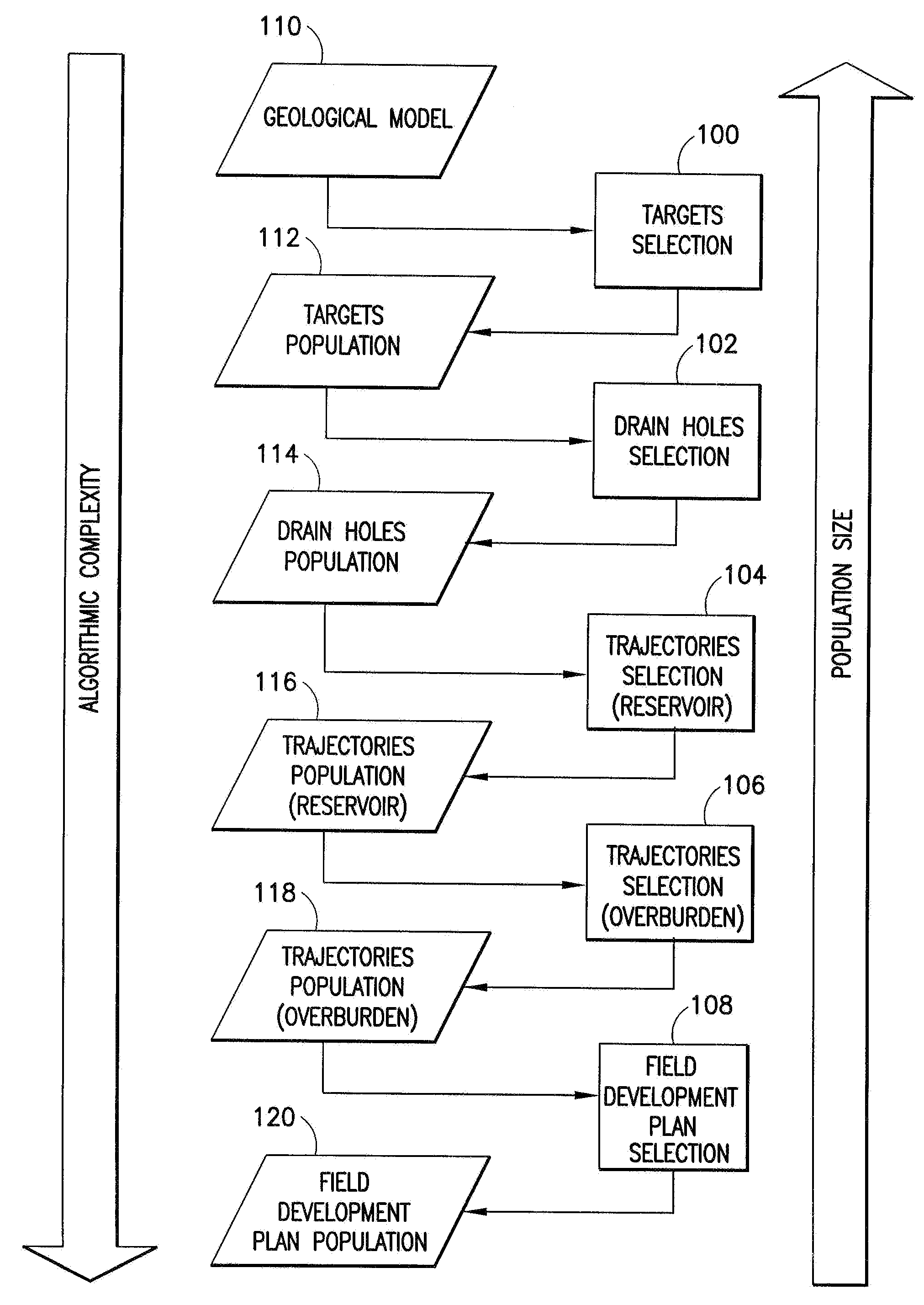
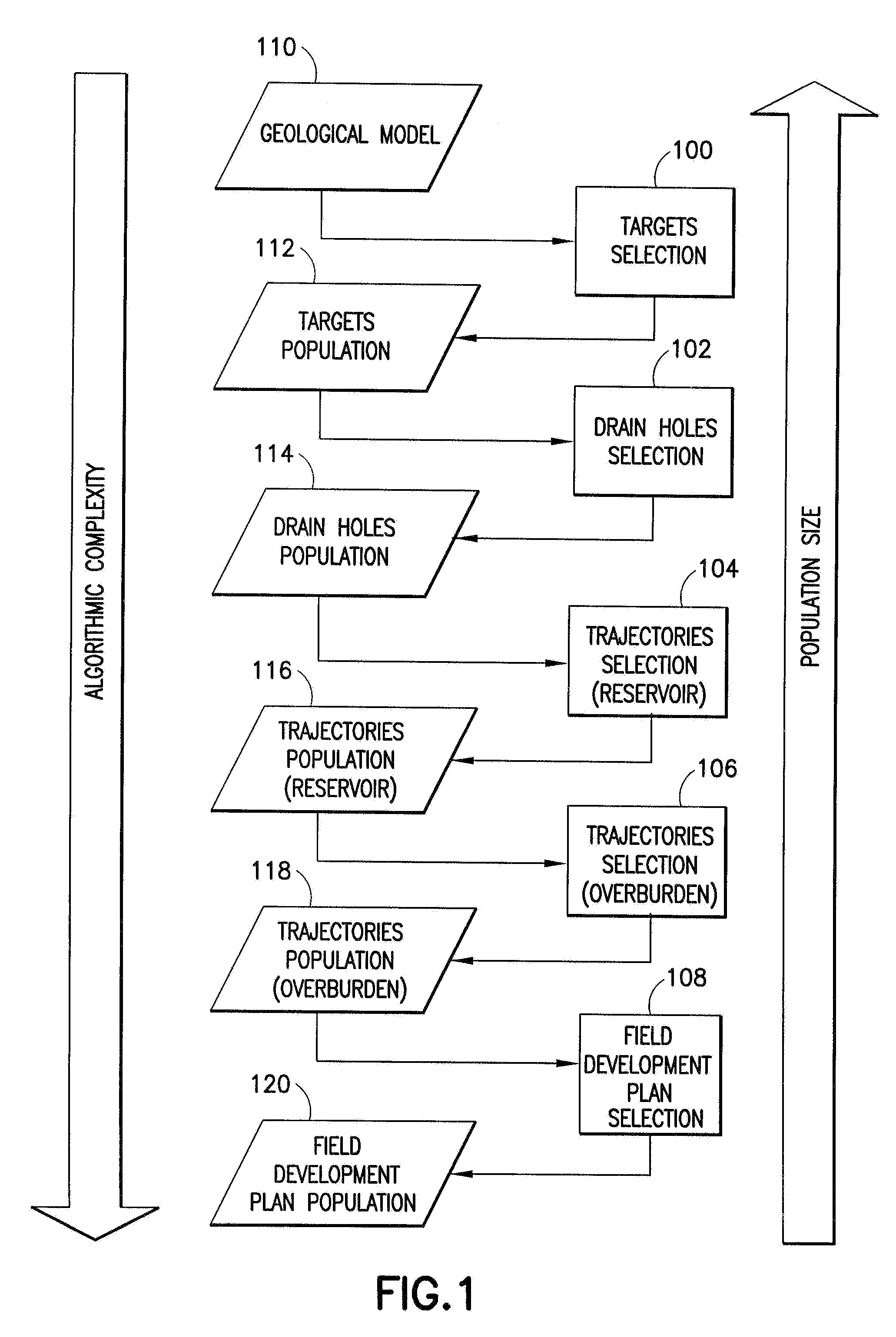
[0004]An automated process for determining the surface and subsurface locations of producing and injecting wells in a field is disclosed. The process involves planning multiple independent sets of wells on a static reservoir model using an automated well planner. The most promising sets of wells are then enhanced with dynamic flow simulation using a cost function, e.g., maximizing either recovery or economic benefit. The process is characterized by a hierarchical workflow which begins with a large population of candidate targets and drain holes operated upon by simple (fast) algorithms, working toward a smaller population operated upon by complex (slower) algorithms. In particular, as the candidate population is reduced in number, more complex and computationally intensive algorithms are utilized. Increasing algorithm complexity as candidate population is reduced tends to produce a solution in less time, without significantly compromising the accuracy of the more complex algorithms.

Problems solved by technology

In particular, as the candidate population is reduced in number, more complex and computationally intensive algorithms are utilized.

Method used


Image

  • Automated field development planning of well and drainage locations
  • Automated field development planning of well and drainage locations
  • Automated field development planning of well and drainage locations

Examples


Embodiment Construction

[0018]FIG. 1 illustrates a technique for automated computation of a FDP including locations of wells and production platforms in an oil or gas field. Workflow is organized into five main operations: target selection (100), drain hole selection (102), reservoir trajectory selection (104), overburden trajectory selection (106), and FDP selection (108).

[0019]The target selection operation (100) is initialized by generating a large initial population (112) of target sets from a geological model (110). For example, 1000 different target sets might be generated, although the actual population size is dependent on the complexity of the field and other considerations. Each member of the population is a complete set of targets to drain the reservoir(s), and each target is characterized by an estimate of its value. For example, a simple value estimate is the associated stock tank oil initially in place (“STOIIP”). In subsequent operations, the large initial population of target sets is gradua...


PUM


Abstract

A hybrid evolutionary algorithm (“HEA”) technique is described for automatically calculating well and drainage locations in a field. The technique includes planning a set of wells on a static reservoir model using an automated well planner tool that designs realistic wells that satisfy drilling and construction constraints. A subset of these locations is then selected based on dynamic flow simulation using a cost function that maximizes recovery or economic benefit. In particular, a large population of candidate targets, drain holes and trajectories is initially created using fast calculation analysis tools of cost and value, and as the workflow proceeds, the population size is reduced in each successive operation, thereby facilitating use of increasingly sophisticated calculation analysis tools for economic valuation of the reservoir while reducing overall time required to obtain the result. In the final operation, only a small number of full reservoir simulations are required for the most promising FDPs.

Description

FIELD OF THE INVENTION[0001]This invention is generally related to oil and gas wells, and more particularly to automatically computing preferred locations of wells and production platforms in an oil or gas field.BACKGROUND OF THE INVENTION[0002]Determining the placement of wells is an important step in exploration and production management. Well placement affects the performance and viability of a field over its entire production life. However, determining optimum well placement, or even good well placement, is a complex problem. For example, the geology and geomechanics of subsurface conditions influence both drilling cost and where wells can be reliably placed. Well trajectories must also avoid those of existing wells. Further, wells have practical drilling and construction constraints. Constraints also exist at the surface, including but not limited to bathymetric and topographic constraints, legal constraints, and constraints related to existing facilities such as platforms and ...

Claims


Application Information

Patent Timeline
IPC IPC(8): G01V9/00G06F19/00
CPCE21B41/00E21B43/30
Inventor TILKE, PETER GERHARDBAILEY, WILLIAM J.COUET, BENOITPRANGE, MICHAELCRICK, MARTIN
Owner SCHLUMBERGER TECH CORP
Learn More