Descent control device

a control device and a technology for preventing excessive speed of descen

Inactive Publication Date: 2008-12-11
MURRAY RICHARD
View PDF8 Cites 19 Cited by
  • Summary
  • Abstract
  • Description
  • Claims
  • Application Information

AI Technical Summary

Benefits of technology

[0003]The principle object of the present invention is to provide a new and improved descent control device that absorbs and evenly distributes converted heat from kinetic energy and prevents excessive speeds of descent which can result in dangerously high impact loads in a fixed rope system.

Problems solved by technology

Such devices are instrumental during firefighters self rescue from untenable elevated positions requiring constant grasp of the rope with an additional problem of rope spiral causing the introduction of pigtails and kinks in the free end prior to entry into the control device.
Of concern is the weight of firefighters coupled with a heavy ensemble of protective clothing and breathing apparatus and then being required to descend several stories while attached to scant 7.5 mm diameter ropes where excessive speed of descent can cause rope breakage during abrupt stoppage of descent.

Method used


Image

  • Descent control device
  • Descent control device

Examples


Embodiment Construction

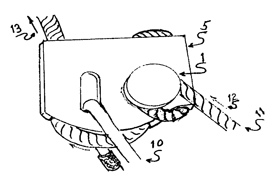
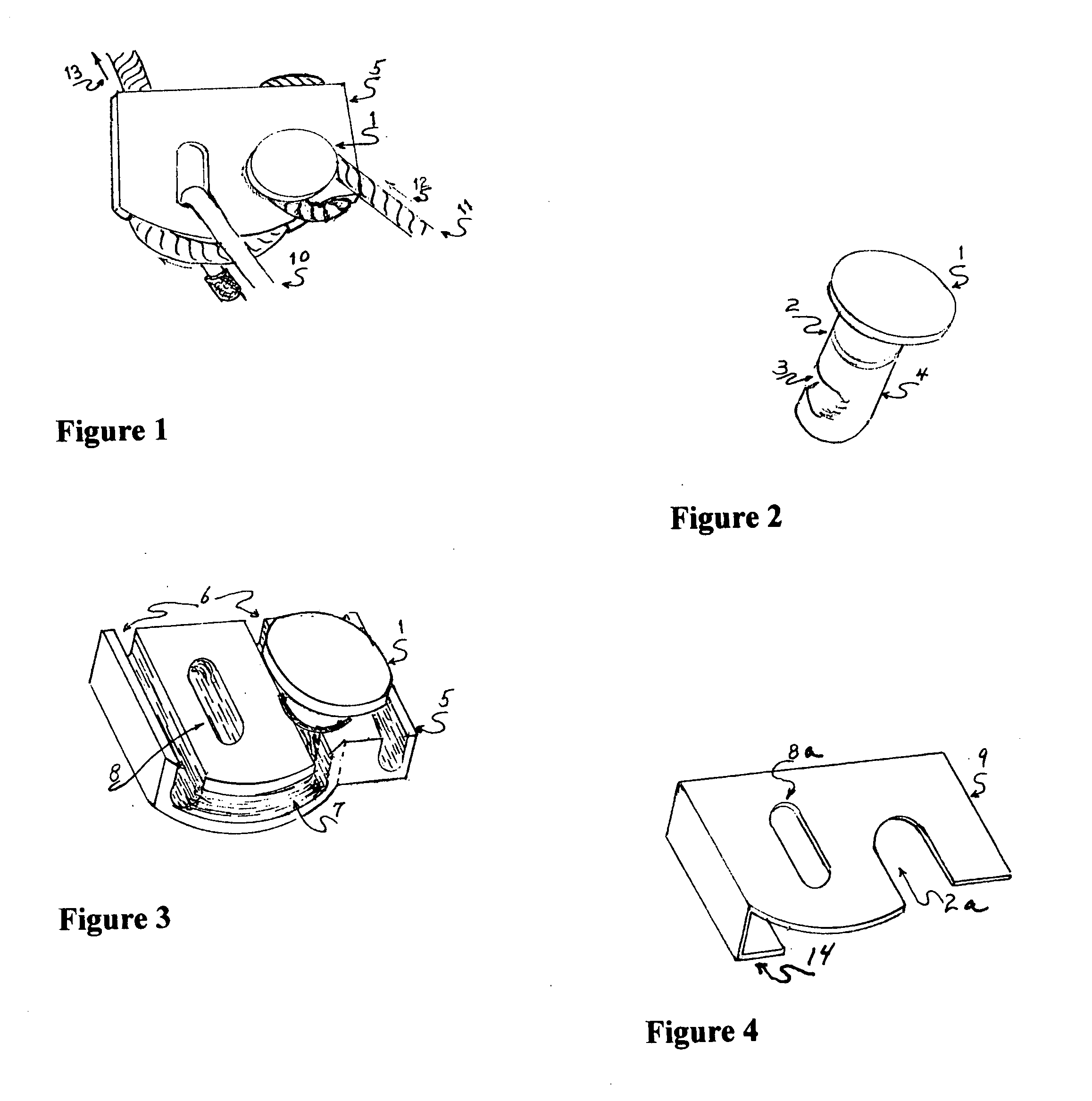
[0011]Turning now descriptively to the drawings, in which similar reference characters denote similar elements throughout the several views, the Figures illustrate a block 5 for a descent control device which consists of channels 6 and furrows 7 for the entry and passage of a rope 11. A mandrel 1 is rotatably secured into the block 5 by means of a set screw (not shown) positioned against the shaft 4 of the mandrel 1. A carabiner 10 is detachably connected to the block 5 through a slotted opening 8 after which the carabiner can in turn be connected to a load bearing harness tie-in point (not shown). Starting at the free end of the rope 12 entry of the rope begins with a single wrap around the mandrel 1 then into the channel (not detailed) and outward 13 to a anchor point.

[0012]As shown in FIGS. 1 and 2 the mandrel 1 has a rotatable shaft 4 where a cam 3 created by a grooved area impinges on a rope 11 as the rope advances through the block 5. One turn of rope 11 is applied to the mand...


PUM


Abstract

This invention relates to a stationary friction-type descent control device for use with an anchored rope and a load supporting harness characterized by a block of metal having several channels spaced by furrows providing benefit of friction and a rotatably fixed mandrel having the simultaneous purpose of first slowing the advancement of rope by friction and secondly by means of said friction causing rotation of the mandrel shaft whereby a cam action impinges upon an advanced section of channeled rope providing yet additional benefit of friction; and with a detachable plate to provide simple access to the channels for sinuously installing an unloaded medial section of rope and with the plate reattached and maintained in place by means of a carabiner positioned through aligned slotted openings in the block and plate a person may descend a rope at a governed rate of speed

Description

BACKGROUND OF THE INVENTION[0001]The instant invention relates generally to descent control devices such as friction or mechanical utilized with a fixed rope where the rope is wrapped around a rod or non-rotatable drum to permit descent by means of grasping the rope and delaying feed of the rope. Such devices are instrumental during firefighters self rescue from untenable elevated positions requiring constant grasp of the rope with an additional problem of rope spiral causing the introduction of pigtails and kinks in the free end prior to entry into the control device. Of concern is the weight of firefighters coupled with a heavy ensemble of protective clothing and breathing apparatus and then being required to descend several stories while attached to scant 7.5 mm diameter ropes where excessive speed of descent can cause rope breakage during abrupt stoppage of descent.[0002]The instant invention relates more specifically to a new improved descent control device that is designed to ...

Claims


Application Information

Patent Timeline
Patent Type & Authority Applications(United States)
IPC IPC(8): A62B1/06
CPCA62B1/14
Inventor MURRAY, RICHARD
Owner MURRAY RICHARD
Why Eureka
Try Eureka