
Sheet conveying device and image forming apparatus

a conveying device and a technology for forming apparatus, applied in the direction of electrographic process apparatus, thin material processing, instruments, etc., can solve the problems of generating distortion, generating distortion, and generating distortion at the primary transferring uni

Inactive Publication Date: 2008-12-11
RICOH KK
View PDF6 Cites 19 Cited by
  • Summary
  • Abstract
  • Description
  • Claims
  • Application Information

AI Technical Summary

Benefits of technology

[0016]It is an object of the present invention to at least partially solve the problems in the conventional technology.

Problems solved by technology

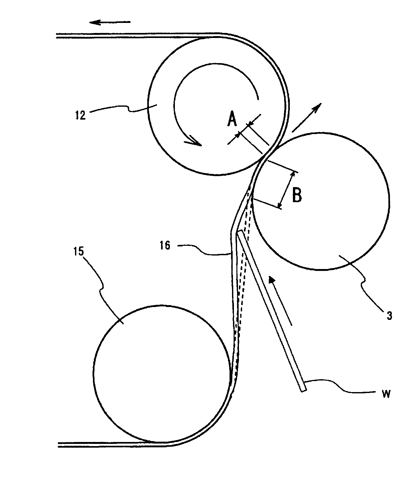
However, when a sheet above a certain thickness enters a secondary transferring unit, the speed of the intermediate transfer body driven at a constant speed up to then fluctuates for a short time, thereby causing a problem of generating a distortion in an image at a primary transferring unit.
In such an apparatus, when the sheet above a certain thickness enters the fixing unit, the speed of a fixing roller or a fixing belt that were driven at a constant speed up to then also fluctuates for a short time, thereby causing the same problem of generating a distortion in an image at the secondary transferring unit.
In the image forming apparatus disclosed in the Japanese Patent Laid-open Publication No. 2003-215870, a fluctuation occurs to the time from the start of printing to the entry of the sheet into the transferring unit, thereby causing an error to the measured time obtained in advance.
Accordingly, it is difficult to obtain the accurate timing for the feedforward control.
In the image forming apparatus disclosed in the Japanese Patent Laid-open Publication No. 2005-107118, similarly to the above, a large fluctuation occurs to the time from the start of clutching of the resist roller to the entry of the sheet into the secondary transferring unit, thereby causing an error to the measured time obtained in advance.
Accordingly, it is difficult to obtain the accurate timing for the feedforward control.
Even with the steady clutching time, in practice, the entry timing of the sheet fluctuates every time, thereby making it difficult to carry out the accurate feedforward control using the value measured in advance, and causing a problem in the accuracy.
Because the entry timing of the sheet changes due to deterioration of parts and deterioration with age, it is difficult to secure stability over time.
However, the timing from the detection of the sheet by the sensor to the entry of the sheet into the fixing unit fluctuates due to the error in the sensor detection position, thereby making it difficult to obtain the accurate timing for the feedforward control.
Moreover, there was a limitation in reducing the distance between the detection sensor and the fixing unit to reduce the detection error, due to the structural restriction.

Method used


Image

  • Sheet conveying device and image forming apparatus
  • Sheet conveying device and image forming apparatus
  • Sheet conveying device and image forming apparatus

Examples


third embodiment

[0086]A sheet conveying device according to a third embodiment, as shown in FIG. 17, includes a second driving unit 7 that rotatably drives the pressure roller 3 (second roller), to the structure of the first embodiment (or second embodiment). The structure that overlaps with the first embodiment is denoted by the same reference numerals, and the descriptions thereof are omitted.

[0087]The second driving unit 7 is a motor supported to the machine frame and electrically connected to the drive control unit 5. The rotation output from the second driving unit 7 is transmitted to the pressure roller 3, via a speed reduction mechanism that includes a small diameter gear 71 fixed to the rotation axis of the motor, and a large diameter gear 31 meshed with the small diameter gear 71 and fixed to an end of the pressure roller 3.

[0088]The sheet conveying device according to the third embodiment formed in this manner completely removes the possibility of generating a glide caused by being rotate...

fourth embodiment

[0090]A sheet conveying device according to a fourth embodiment includes a feedforward reference value producing unit that produces a feedforward reference value, based on the speed fluctuation of the endless belt generated to the nip portion when the sheet is conveyed. The reason to include the feedforward reference value producing unit is as follows:

[0091]With the sheet conveying device, even when the same type of the paper is used, the speed fluctuation of the belt generated when the paper enters the nip portion changes, depending on the usage environment and the individual variety of the machine to be used. Therefore, the optimal control effect may not be achieved, when the feedforward reference value set in advance is used.

[0092]An example will now be explained with reference to FIGS. 18A and 18B. As shown in FIG. 18A, when the difference exists in the amplitude between the assumed speed fluctuation (solid line) and the actual speed fluctuation (dotted line), the speed fluctuat...


PUM


Abstract

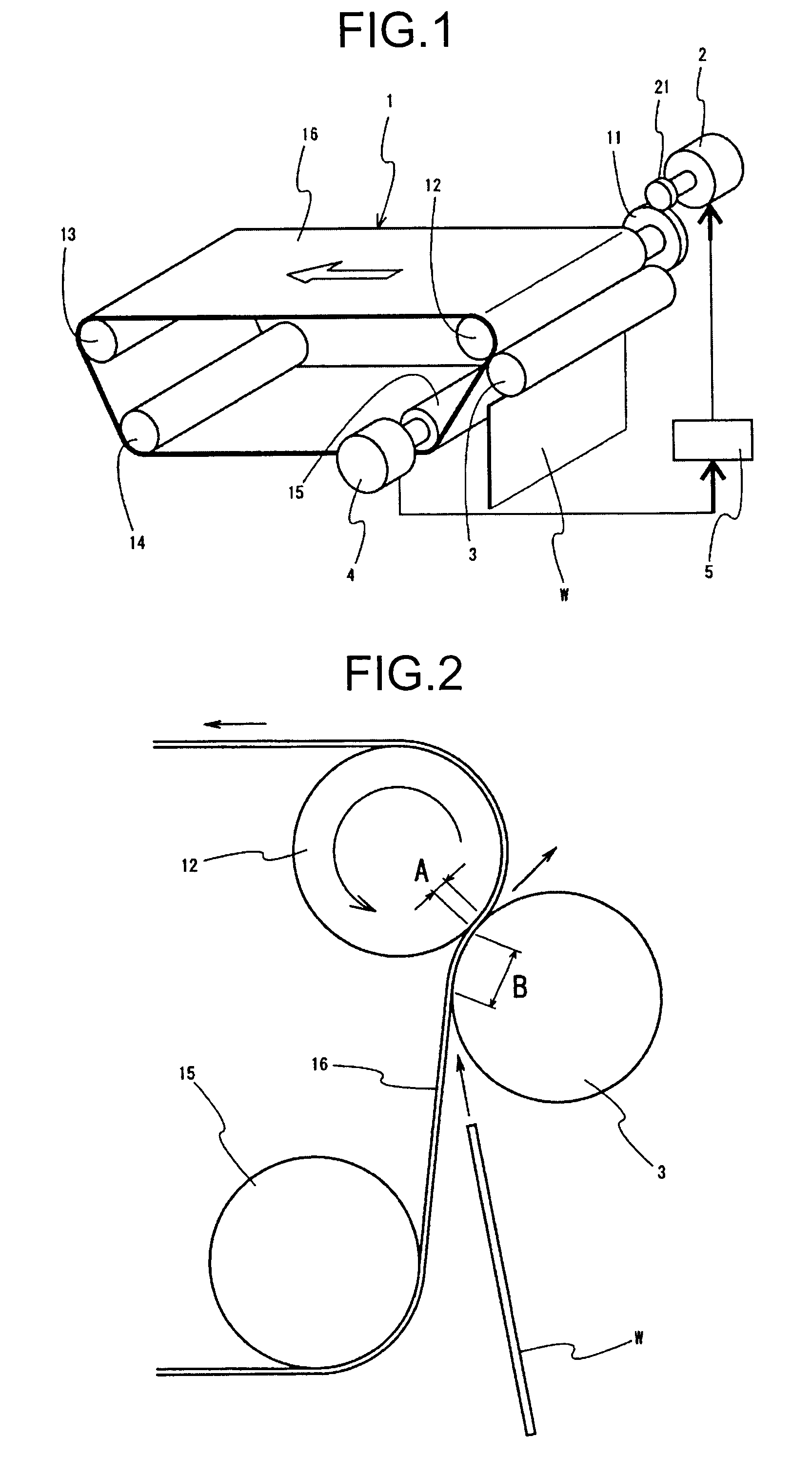
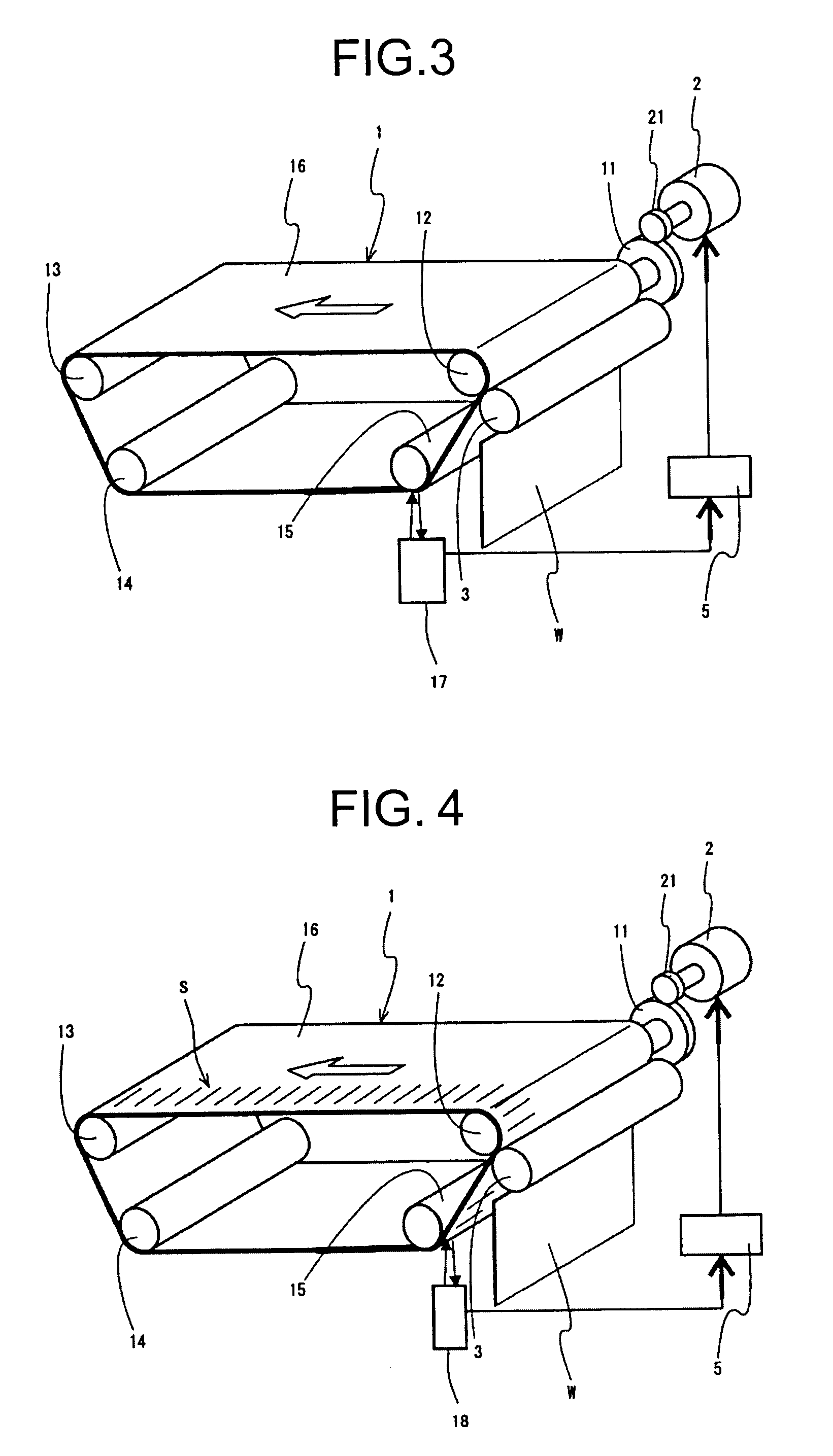
A fluctuation detecting unit detects a fluctuation of an endless belt generated when a sheet is brought into contact with a predetermined position of the endless belt at an upstream side in a conveying direction from a nip portion based on fluctuation information acquired by a fluctuation information acquiring unit. An entry timing estimating unit estimates entry timing of the sheet into the nip portion based on a detection of the fluctuation. A correction control unit corrects a speed fluctuation of the endless belt generated when the sheet enters the nip portion by performing a feedforward control of a first driving unit based on the entry timing.

Description

CROSS-REFERENCE TO RELATED APPLICATIONS[0001]The present application claims priority to and incorporates by reference the entire contents of Japanese priority documents, 2007-153189 filed in Japan on Jun. 8, 2007 and 2007-312276 filed in Japan on Dec. 3, 2007.BACKGROUND OF THE INVENTION[0002]1. Field of the Invention[0003]The present invention relates to a sheet conveying device and an image forming apparatus that includes the sheet conveying device.[0004]2. Description of the Related Art[0005]In recent years, in color image forming apparatuses, an intermediate transfer method that primarily transfers a toner image on a photosensitive body on an intermediate transfer body, and then secondarily transfers the toner image in four colors on the intermediate transfer body on a sheet has been widely used. The image forming apparatus using the intermediate transfer body has an advantage of high versatility that various types of sheets such as a thin paper, a thick paper, a postcard, and an...

Claims


Application Information

Patent Timeline
Patent Type & Authority Applications(United States)
IPC IPC(8): B65H5/02
CPCG03G15/657G03G2215/00409G03G15/6564G03G2215/00645G03G2215/0154G03G2215/00413
Inventor NOGUCHI, HIDETAKAANDOH, TOSHIYUKIHODOSHIMA, TAKASHIOIKAWA, TATSUHIKOHOSHINO, SEIJIMATSUDA, HIROMICHIKOMATSU, MAKOTOHASHIMOTO, TAKASHI
Owner RICOH KK
Learn More