Methods and apparatuses for non-optical pixel self test

a self-testing, non-optical technology, applied in the direction of instruments, television systems, television system scanning details, etc., can solve the problems of inability to easily test pixels b>10/b> of the imaging device by end users of the device to make adjustments over the life of the imaging devi

Active Publication Date: 2008-12-11
APTINA IMAGING CORP
View PDF11 Cites 18 Cited by
  • Summary
  • Abstract
  • Description
  • Claims
  • Application Information

AI Technical Summary

Problems solved by technology

Conventional testing is time consuming and requires analysis of the performance of the imaging device when exposed to a light source.
In addition to the time needed for optical testing, significant time is needed to set up conventional testing equipment.
Further, with conventional testing techniques, the pixels 10 of the imaging device can not readily be tested by end users of the device to make adjustments over the life of the imaging device.

Method used


Image

  • Methods and apparatuses for non-optical pixel self test
  • Methods and apparatuses for non-optical pixel self test
  • Methods and apparatuses for non-optical pixel self test

Examples


Embodiment Construction

[0012]In the following detailed description, reference is made to the accompanying drawings which form a part hereof, and in which is shown by way of illustration specific embodiments in which the invention may be practiced. These embodiments are described in sufficient detail to enable those of ordinary skill in the art to make and use them, and it is to be understood that structural, logical, or procedural changes may be made to the specific embodiments disclosed.

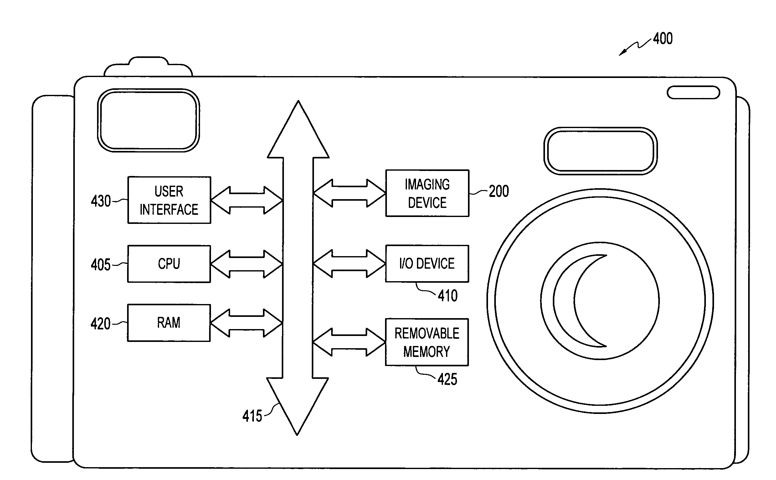
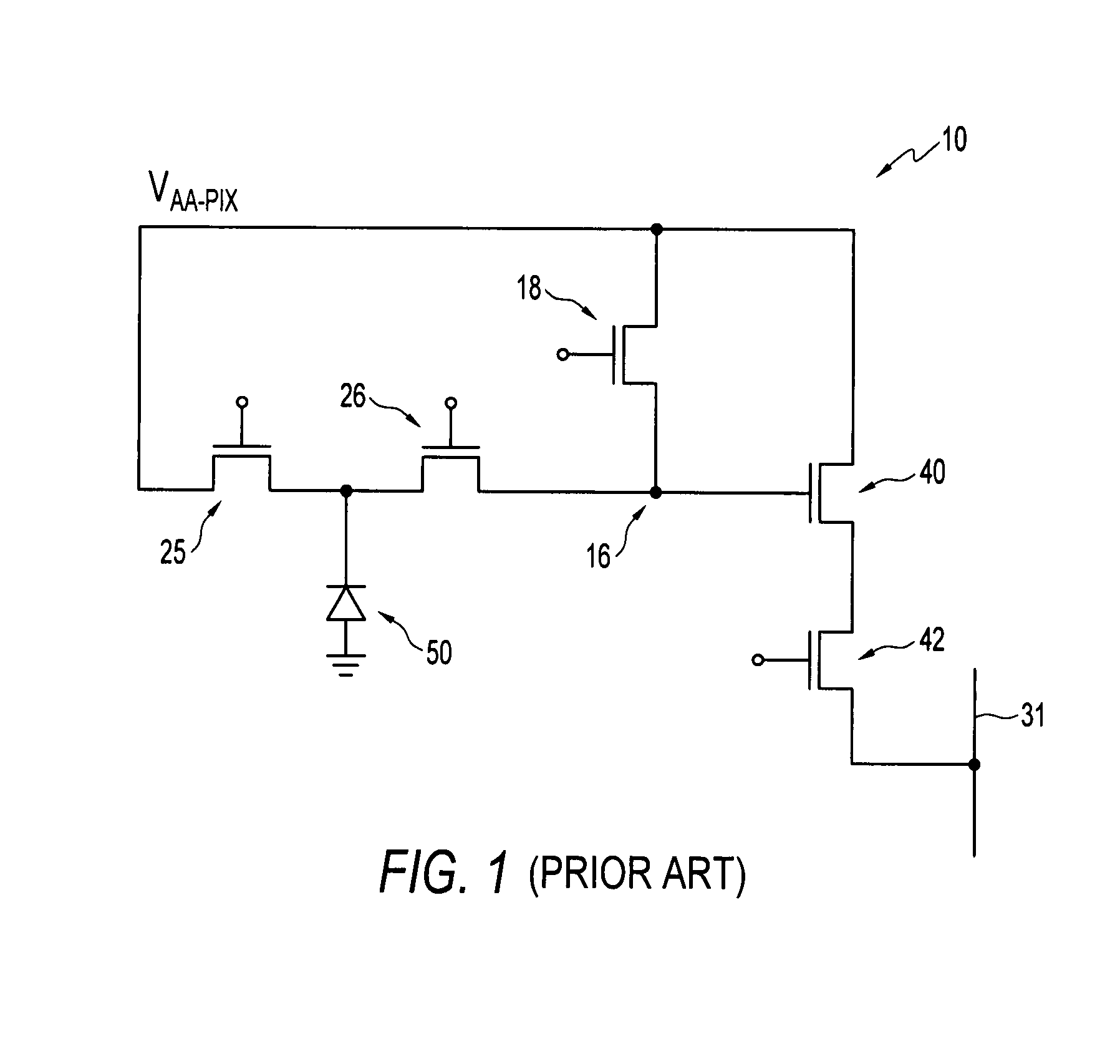
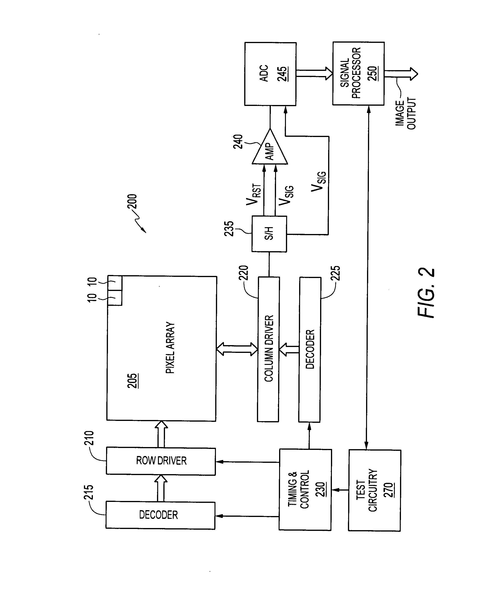
[0013]FIG. 2 shows a CMOS imaging device 200. The imaging device 200 includes a pixel array 205 having a plurality of pixels 10 (FIG. 1) arranged in columns and rows. It should be noted that although pixel 10 is shown as a 5-transistor (5T) configuration with an antiblooming transistor 26, other pixel configurations may be employed in imaging device 200. For example, pixels can include a shutter transistor coupled between the photoconversion device 50 and the transfer transistor 26 to have a 6-transistor (6T) configuratio...


PUM


Abstract

Methods and apparatuses for non-optical testing of imaging devices having an array of pixels are provided. One or more pixels are tested by setting the photoconversion device and / or a floating diffusion region to a known voltage level that is different from that used to operate the pixel during non-test operation. The pixel is then sampled and compared to an expected value.

Description

FIELD OF THE INVENTION[0001]The embodiments described herein relate generally to imaging devices and, more specifically, to a method and apparatus for testing pixels employed in such devices.BACKGROUND OF THE INVENTION[0002]Solid state imaging devices, including charge coupled devices (CCD), CMOS imaging devices, and others, have been used in photo imaging applications. A solid state imaging device circuit includes a focal plane array of pixel cells or pixels, each one including a photoconversion device, which may be a photogate, photoconductor, or a photodiode having a doped region for accumulating photo-generated charge. For CMOS imaging devices, each pixel has a charge storage region, formed on or in the substrate, which is connected to the gate of an output transistor that is part of a readout circuit. The charge storage region may be constructed as a floating diffusion region. In some CMOS imaging devices, each pixel may further include at least one electronic device such as a ...

Claims


Application Information

Patent Timeline
Patent Type & Authority Applications(United States)
IPC IPC(8): H04N5/228H04N5/335H04N17/00H04N17/02
CPCH04N5/357H04N17/002H04N25/60
Inventor CHINNAVEERAPPAN, KALAIRAJA
Owner APTINA IMAGING CORP
Why Eureka
Try Eureka