LED display screen field testing apparatus and method

A technology for LED display and on-site testing, applied in the direction of testing optical performance, etc., can solve the problems of inconsistent installation environment of LED display, not representing the overall performance of LED display, inconvenient testing, etc. The effect of fast handling and strong environmental adaptability

Active Publication Date: 2015-12-16
光机电(广州)科技研究院有限公司
View PDF6 Cites 12 Cited by
  • Summary
  • Abstract
  • Description
  • Claims
  • Application Information

AI Technical Summary

Problems solved by technology

However, for larger LED displays, the performance parameters of a single display module or module cannot represent the overall performance of the entire LED display
[0003] For a large number of LED displays used outdoors, on-site inspections are required during installation and commissioning, engineering acceptance, and delivery. The inspection items include brightness, brightness uniformity, brightness identification level, gray scale, contrast, and white field color. Coordinates, viewing angles, dominant wavelength errors, etc., generally use test instruments such as chroma luminance meters or spectroradiometers, but due to the inconsistency and complexity of the LED display installation environment, especially outdoor LED displays are generally installed at higher places, It is difficult to find a suitable location with the same height to place the optical test device, and the hand-held optical test device often brings greater test inconvenience and test error

Method used


Image

  • LED display screen field testing apparatus and method
  • LED display screen field testing apparatus and method

Examples


Embodiment Construction

[0027] The present invention will be further described below in conjunction with specific examples.

[0028] The LED display field testing device described in this embodiment includes hardware and software:

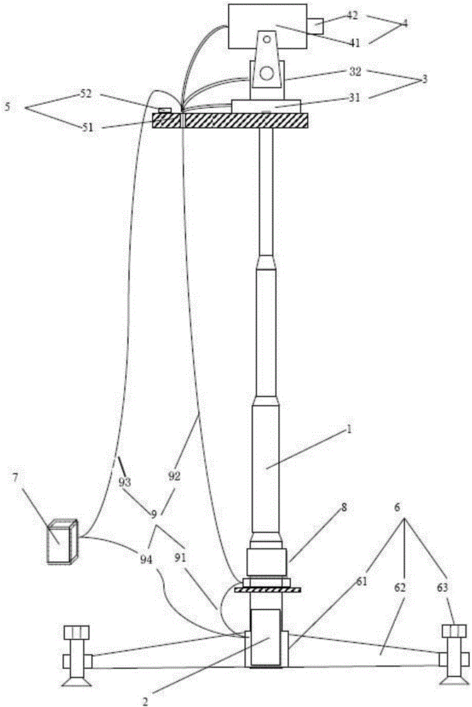
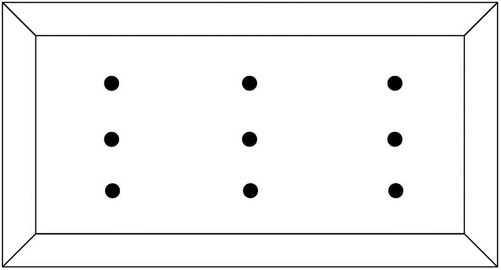
[0029] Such as figure 1 , 2 , the hardware part includes a pneumatic lifting rod 1, an air pump 2, an optical test device 4, a reference platform 5, a fixed base 6, a portable power supply 7, a computer 8 and a three-dimensional rotating platform 3 with a driving device, such as figure 1 As shown, wherein, the pneumatic lifting rod 1 is installed vertically and detachably on the fixed base 6, and is driven by the air pump 2 to realize free expansion and contraction; the reference platform 5 is horizontally and detachably installed on the top of the pneumatic lifting rod 1, through Adjust the adjustment balance stud 502 of the fixed base 6 to adjust the levelness of the reference platform 5, to ensure that the lower surface of the three-dimensional rotating platform 3 is...


PUM


Abstract

The invention discloses an LED display screen field testing apparatus comprising a pneumatic lifting rod, an air pump, an optical testing device, a reference platform, a fixing pedestal, a portable power supply, a computer, and a three-dimensional rotary holder. The pneumatic lifting rod is vertically installed on the fixing pedestal and is driven by the air pump to stretch and retract. The reference platform is horizontally installed on the top of the pneumatic lifting rod. The three-dimensional rotary holder is installed on the reference platform and is driven by a driving device to perform three-dimensional rotation. The optical testing device is installed on the three-dimensional rotary holder. The computer is used for acquiring and displaying images captured by the optical testing device in real time. By controlling the pneumatic lifting rod to ascend and descend and controlling the three-dimensional rotary holder to perform three-dimensional rotation, the optical testing device is driven to freely ascend, descend, and three-dimensionally rotate. The portable power supply supplies power to the air pump, the optical testing device, the computer, and the driving device. The testing apparatus and testing method have advantages of high testing accuracy, good environment suitability, convenient installation and transport, and high automation degree.

Description

technical field [0001] The invention relates to the field of LED semiconductor lighting detection, in particular to an on-site testing device and testing method for an LED display screen. Background technique [0002] At present, there are clear testing standards for the testing of the optical characteristics of LED displays, including laboratory testing and on-site testing. Laboratory testing items include brightness, brightness uniformity, brightness identification level, gray scale, contrast, and white field color coordinates. , Angle of view, refresh frequency, dominant wavelength error, etc., generally refer to the traditional liquid crystal screen detection method, there is a special automatic test system for the optical characteristics of the display screen, which is mainly composed of a five-axis turntable, a trace-type optical test device and a signal source. Due to the limitations of space and the structure of the laboratory display test system, it can basically on...

Claims


Application Information

Patent Timeline
Patent Type & Authority Applications(China)
IPC IPC(8): G01M11/02
Inventor 王巧彬任豪翁纪钊高军翔
Owner 光机电(广州)科技研究院有限公司
Why Eureka
Try Eureka