
Moving imager camera for track and range capture

Inactive Publication Date: 2008-12-11
INTERVAL RESEARCH CORPORATION
View PDF54 Cites 5 Cited by
  • Summary
  • Abstract
  • Description
  • Claims
  • Application Information

AI Technical Summary

Benefits of technology

"The present invention is a multi-image camera system that provides high-resolution broad field coverage over a wide range of subject distances while retaining the epipolar constraints necessary for efficient stereo matching. It supports both monocular and object tracking applications. The imaging device is placed on a three-degree-of-freedom linear motion platform, which allows for accurate positioning and stable frame of reference for scene computation. The system also utilizes a wide-angle lens and a spherical camera for efficient and economical imaging. The invention provides an economical solution to the problems of the prior art and offers advantages such as excellent optical resolution, greater simplicity, increased undistorted field of view, and opportunities for studying human psychophysical behavior."

Problems solved by technology

Image focus may be attained through the traditional rotating-travel focus adjustment although, for quantitative computational tasks, this is often unsatisfactory as the center of projection may vary with lens rotation.

Method used


Image

  • Moving imager camera for track and range capture
  • Moving imager camera for track and range capture
  • Moving imager camera for track and range capture

Examples


Embodiment Construction

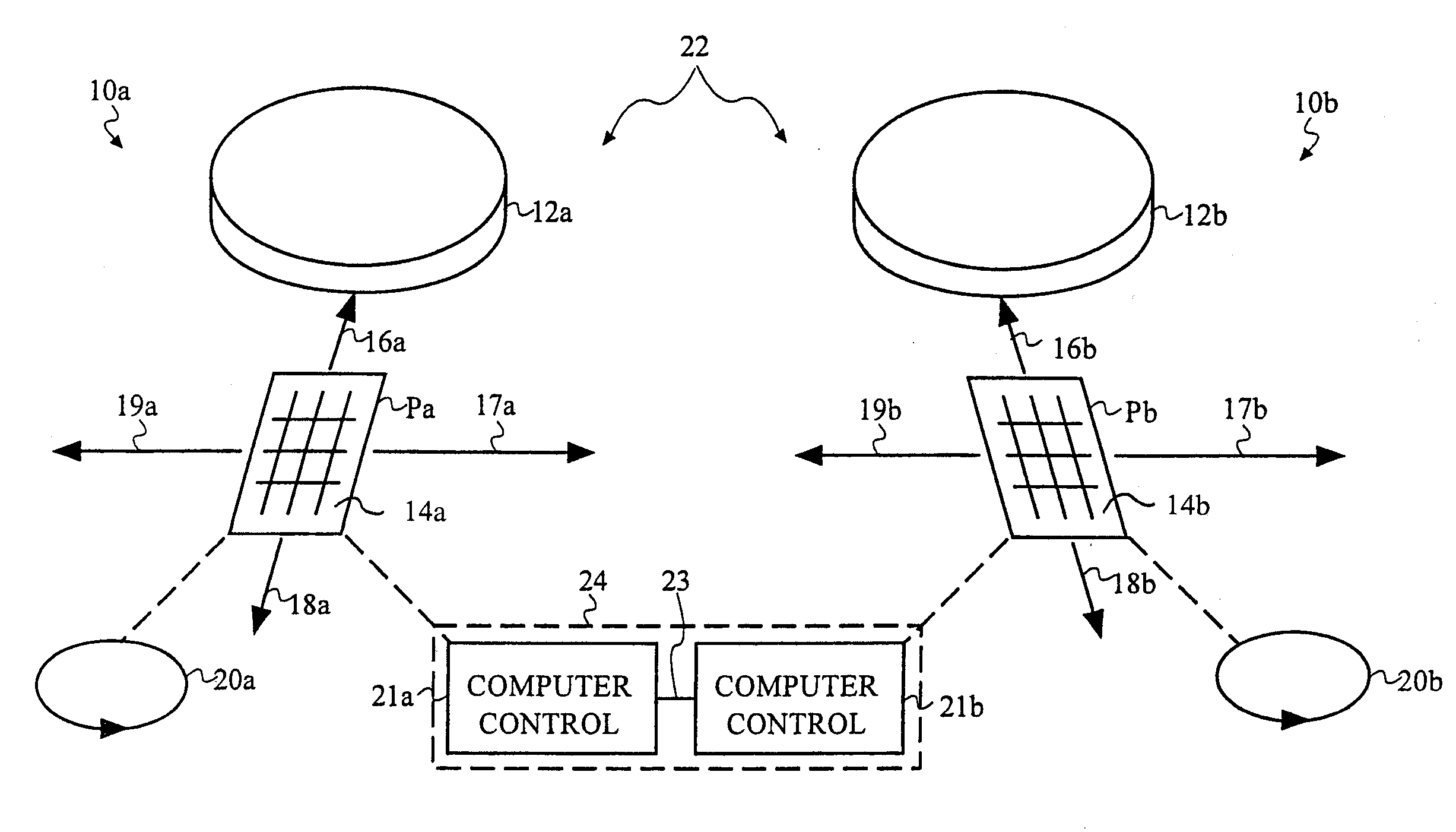
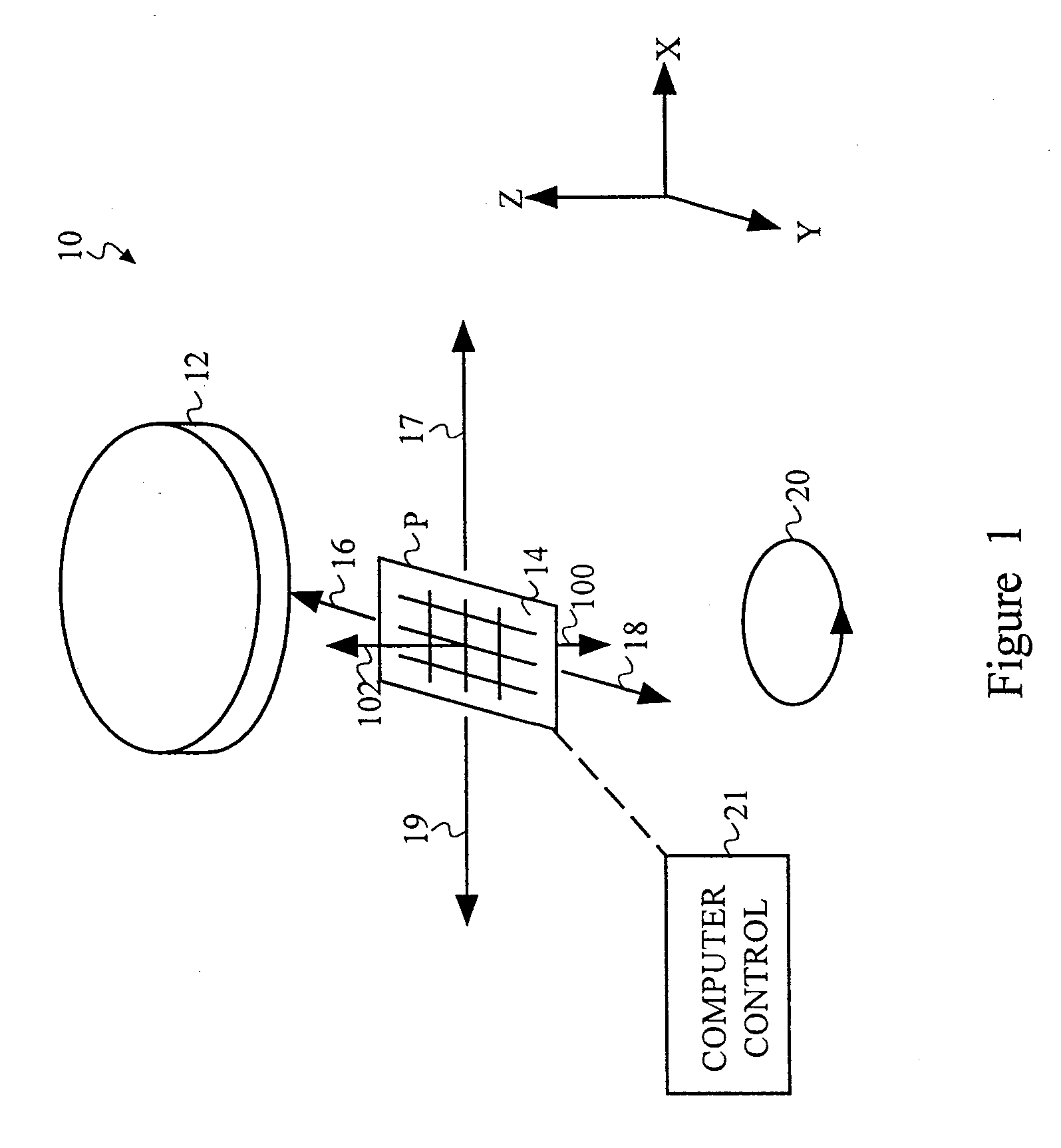
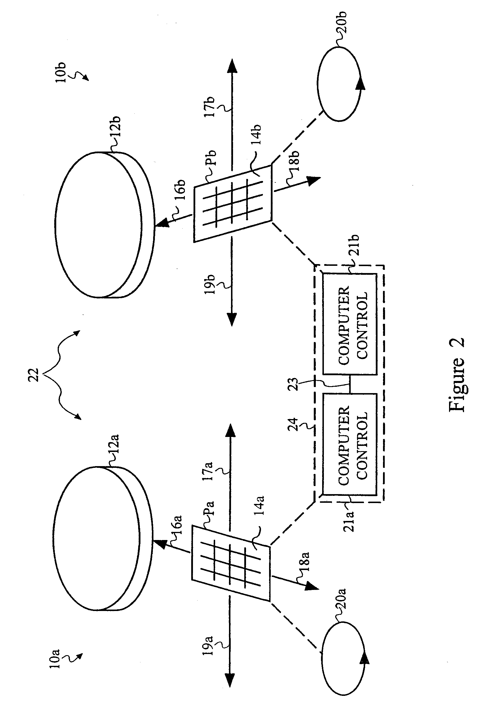
[0030]With reference to FIG. 1, a monocular imager apparatus or moving imager “camera”10 in accordance with one embodiment of the present invention will now be described. The moving imager camera 10 includes a lens 12, and an imaging array, imaging device, or “imager”14. As indicated by the arrows 16, 17, 18, 19, 100, and 102, the imager is capable of independent motion along the three degrees of freedom defined by an X-Y-Z axis. This means that the imager 14 can move both in-plane and out-of-plane with respect to the lens 12 for view selection and focus, and may also be synchronized for rectangular displacements 20 in the imager plane P to provide super-resolution frame integration. The displacements 20 are preferably rectangular, although they are represented by a circle in this figure. As will be appreciated by those skilled in the art, “rectangular” means any appropriate movement of the imager in the plane P to provide the necessary local sampling. For example, these rectangular...


PUM


Abstract

A precision motion platform carrying an imaging device under a large-field-coverage lens enables capture of high resolution imagery over the full field in an instantaneous telephoto mode and wide-angle coverage through temporal integration. The device permits automated tracking and scanning without movement of a camera body or lens. Coupled use of two or more devices enables automated range computation without the need for subsequent epipolar rectification. The imager motion enables sample integration for resolution enhancement. The control methods for imager positioning enable decreasing the blur caused by both the motion of the moving imager or the motion of an object's image that the imager is intended to capture.

Description

CROSS-REFERENCE TO RELATED APPLICATION[0001]This application claims the benefit of Baker et al.'s copending U.S. Provisional Patent Application No. 60 / 302,761, entitled “MOVING IMAGER CAMERA FOR TRACKING, SCANNING, RANGE AND SUPER-RESOLUTION,” filed Dec. 11, 1996, which is incorporated herein by reference in its entirety. This application is related to Woodfill et al.'s copending U.S. patent application Ser. No. 08 / 839,767, filed Apr. 28, 1997, entitled “Data Processing System and Method,” which is incorporated herein by reference in its entirety.TECHNICAL FIELD[0002]This invention relates generally to computer input devices, and more particularly to digital image capture devices used to provide ranging and tracking information for a computer system.BACKGROUND ART[0003]The range of an object, i.e. the distance to the object from an observation site, can be determined by the analysis of two or more spatially separated images (often referred to as “binocular images” when there are two...

Claims


Application Information

Patent Timeline
Patent Type & Authority Applications(United States)
IPC IPC(8): H04N5/228H04N5/225G01C11/02H04N23/40
CPCG01C11/02
Inventor BAKER, HENRY H.WOODFILL, JOHN I.ST. HILAIRE, PIERREKALAYJIAN, NICHOLAS R.
Owner INTERVAL RESEARCH CORPORATION
Learn More