System and method for improved computational imaging

a computational imaging and image processing technology, applied in the field of computational imaging, can solve the problems of reducing the depth-of-field (dof) of the resultant image, reducing the spatial and longitudinal resolution, and not recovering the information about the real-world scene, so as to enhance the depth-of-field image and spatial temporal resolution. , the effect of enhancing the depth-of-field imag

Inactive Publication Date: 2017-05-11
DUKE UNIV
View PDF1 Cites 2 Cited by
  • Summary
  • Abstract
  • Description
  • Claims
  • Application Information

AI Technical Summary

Benefits of technology

[0011]The present invention enables a system and method for computing a digital image of a scene such that the resultant image has enhanced spatial, temporal, and / or depth resolution without some of the costs and disadvantages of the prior art. Embodiments of the present invention are well suited to forming high-resolution images, such as three-dimensional images and / or enhanced depth-of-field images of the scene. Further, the augmented information can be recovered during a single image frame, making real-time imaging applications, such as three-dimensional video, feasible.

Problems solved by technology

As a result, a great deal of information about the real-world scene is not recovered by the recording medium, thereby degrading spatial and longitudinal resolution and limiting the depth-of-field (DOF) of the resultant image.
Unfortunately, this conventional strategy does not account for the three-dimensional spatial structure of the object space of the scene.
Unfortunately, prior-art coded-aperture-imaging approaches are non-ideal because: (1) relay optics used to image the code plane onto the detector increase the complexity and volume of the optical system; and (2) accurate characterization of the forward model is challenging.

Method used


Image

  • System and method for improved computational imaging
  • System and method for improved computational imaging
  • System and method for improved computational imaging

Examples


Embodiment Construction

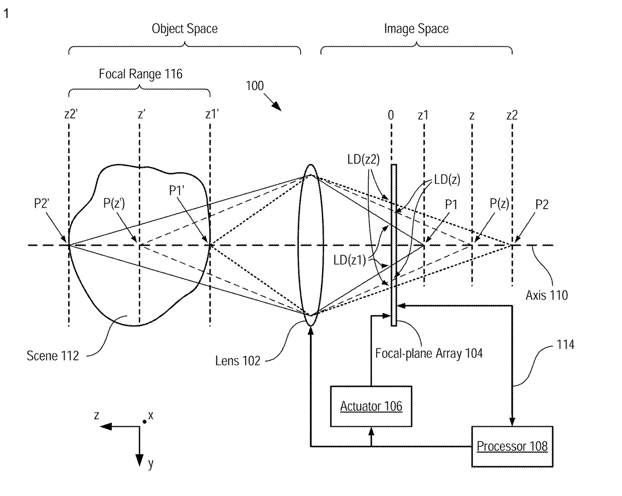
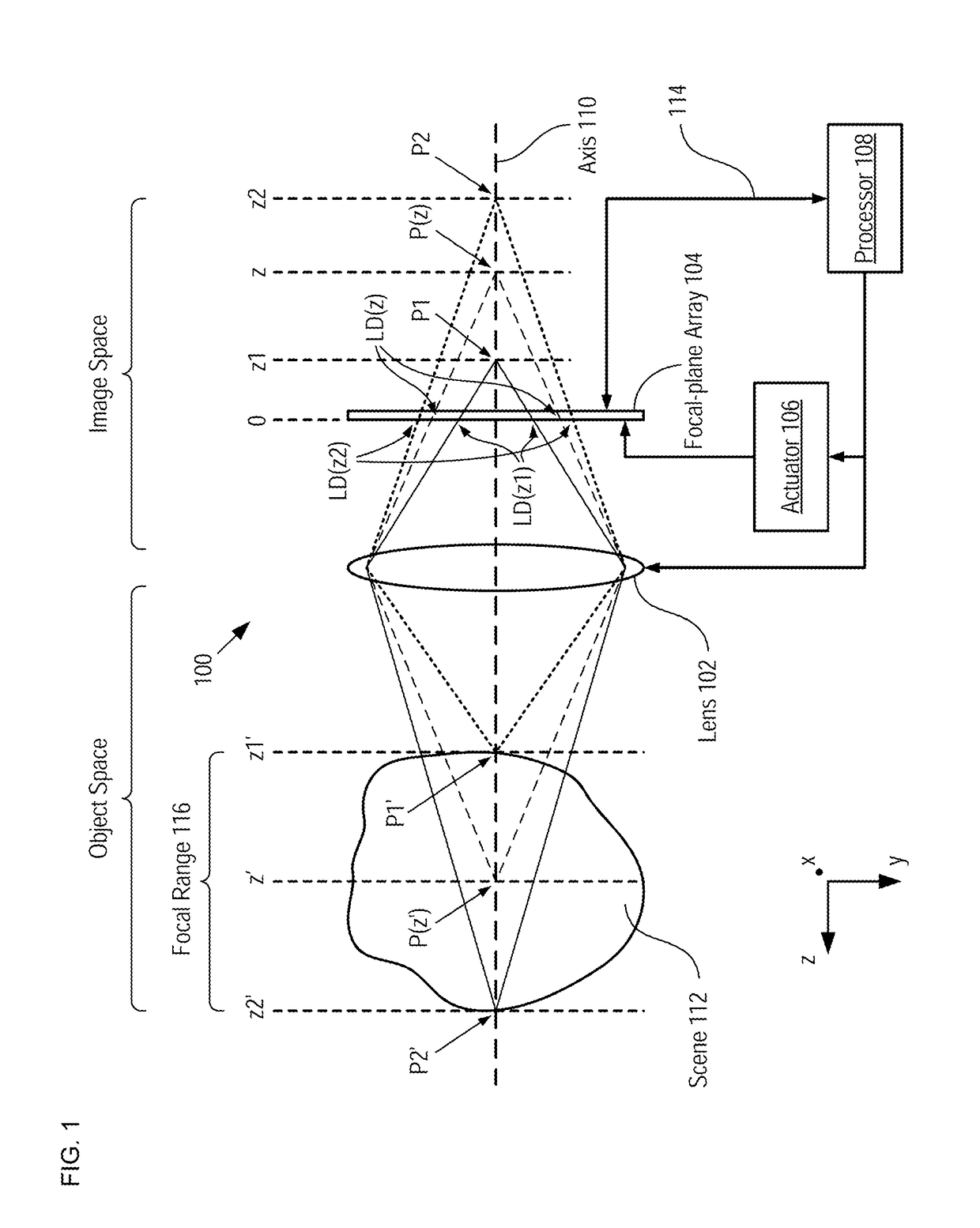
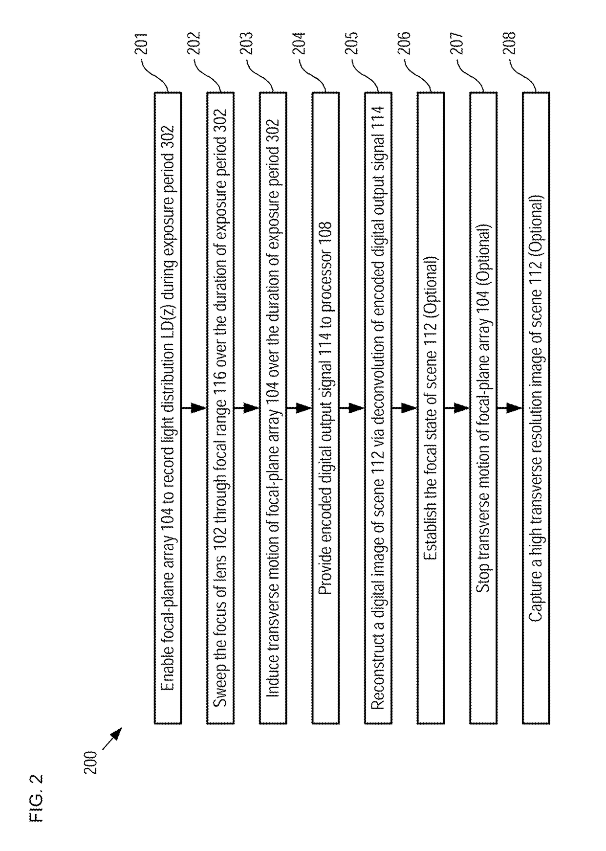
[0045]Embodiments of the present invention employ image translation as a coding mechanism to improve the quality of a reconstructed image in computational imaging systems. Specifically, the image translation includes simultaneous relative lateral and longitudinal motion between a focal-plane array of the imaging system and a physical light distribution provided to it by the optics of the imaging system during each exposure frame of the imaging system.

[0046]Computational imaging relies on a model for the physical image capture process, wherein the image, g(x,y,z,t) (where x, y, and z are spatial coordinates in the image space of lens 102) is a function of the physical measurements f(x′,y′,z′,λ,t) of the scene being imaged (where x′, y′, and z′ are spatial coordinates in the object space of lens 102), as influenced by the optical characteristics of the imaging system—specifically, its PSF, h(x,x′,y,y′,z,z′,λ). Actual measurements in a modern digital imaging system consist of discrete ...


PUM


Abstract

A system and method for computing a digital image of a scene, where the digital image contains enhanced depth information are disclosed. Embodiments of the present invention form a light distribution on a focal-plane array, where the light distribution is based on an optical image of the scene formed by a lens system. During the exposure period of the focal-plane array, longitudinal and transverse motion are imparted between the light distribution and the focal-plane array, which encodes depth information on the blur kernel of the lens system, thereby generating an encoded digital output signal. A depth-information-enhanced digital image of the scene is computed by deconvolving the encoded digital output signal with the blur kernel of the lens system and a model of the transverse motion.

Description

CROSS REFERENCE TO RELATED APPLICATIONS[0001]This application claims the benefit of U.S. Provisional Application Ser. No. 62 / 011,129, filed Jun. 12, 2014, entitled “Systems and Methods for Image Translation for Computational Imaging,” (Attorney Docket DU4366PROV), which is incorporated by reference. If there are any contradictions or inconsistencies in language between this application and one or more of the cases that have been incorporated by reference that might affect the interpretation of the claims in this case, the claims in this case should be interpreted to be consistent with the language in this case.FIELD OF THE INVENTION[0002]The present invention relates to computational imaging in general, and, more particularly, to forming digital images having improved quality, such as three-dimensional images and extended depth-of-field images.BACKGROUND OF THE INVENTION[0003]A camera is an optical instrument in which a lens system captures light from a scene and forms an optical im...

Claims


Application Information

Patent Timeline
Patent Type & Authority Applications(United States)
IPC IPC(8): G06T7/571H04N5/225
CPCG06T7/571H04N5/2254G06T2207/10052G06T2207/10144G06T2200/21G06T2207/10028G06T5/50G06T2207/10148G06T2207/20221
Inventor BRADY, DAVID JONESCARIN, LAWRENCE L.LIULL, PATRICK R.YUAN, XIN
Owner DUKE UNIV
Why Eureka
Try Eureka