Screen and projection system using the same

a projection system and screen technology, applied in the field of front screens, can solve the problems of cost driving, screen according to patent literature 2 cannot be widely utilized, and the requirement of lenticular lenses to correspond the pixel,

Inactive Publication Date: 2008-12-11
YAMAUCHI NAOFUMI
View PDF6 Cites 9 Cited by
  • Summary
  • Abstract
  • Description
  • Claims
  • Application Information

AI Technical Summary

Benefits of technology

[0015]According to the present invention, a front screen and an image projection system can be realized that can provide a wide viewing angle and that is optimized to the observation condition.

Problems solved by technology

However, front screens utilizing directional diffusing sheets according to the patent literature 1 could not achieve both: widening the viewing angle range to the left and right direction as well as cutting off light from the illumination.
Also, screens according to patent literature 2 cannot be widely utilized and the requirement of the application of lenticular lenses to correspond the pixel is cost driving.
Furthermore, the increase of the viewing angle is limited due to the light-absorbing layer, that is also absorbing utilized light so that the light efficiency is bad and results in darkening.

Method used


Image

  • Screen and projection system using the same
  • Screen and projection system using the same
  • Screen and projection system using the same

Examples


first embodiment

of Light-Reflecting Layer

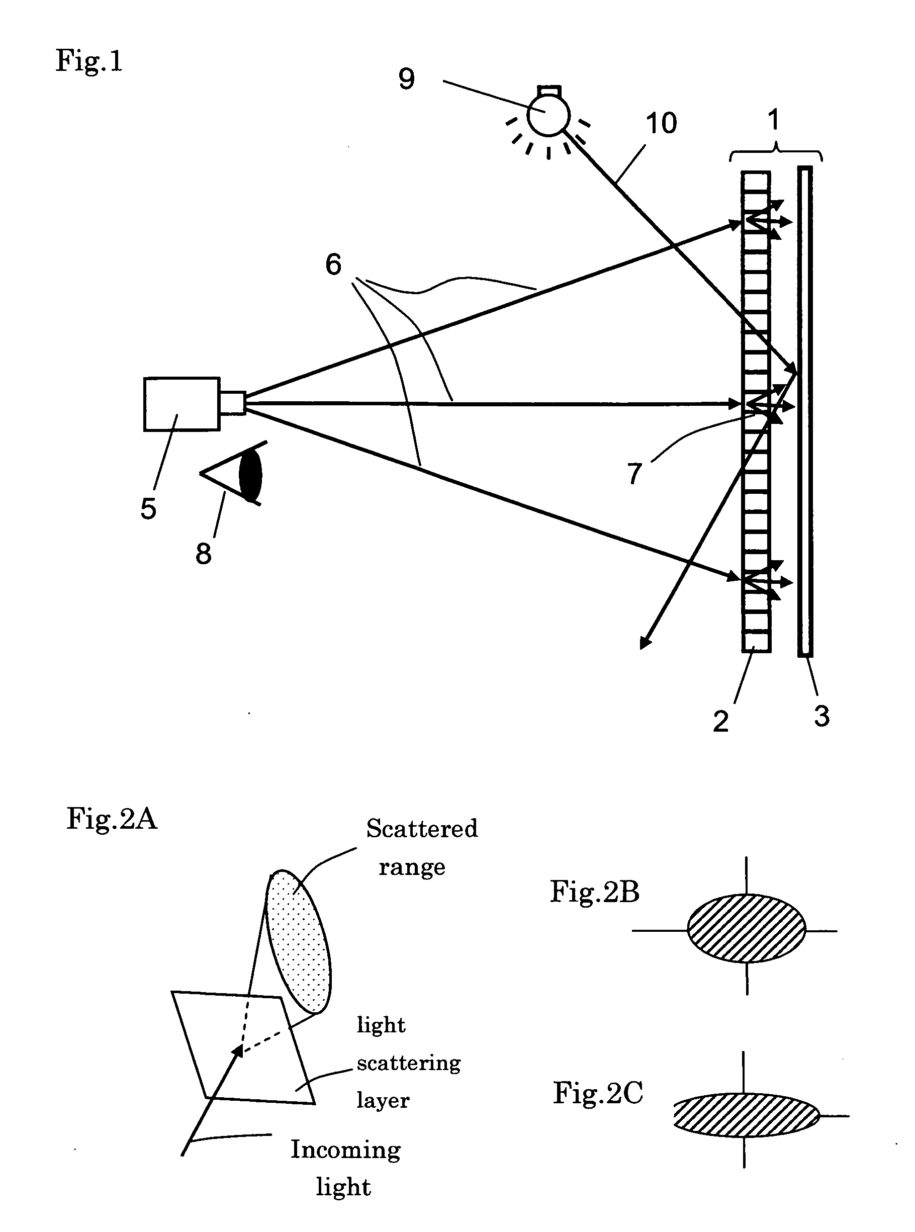
[0055]FIG. 5 provides a scheme of an example for the light-reflecting layer. According to the FIG., a plurality of light-reflecting elements 4 are randomly formed in the light-reflecting layer 3. In this case the reflecting elements 4 are positioned such that the scattering field in the left and right direction is wider than in the up and down direction.

[0056]The areas, in which light-reflecting elements 4 are formed scatters light, whereas areas, in which no reflecting elements 4 are formed simply reflect light.

[0057]This means that the anisotropy in the scattered reflection increases with the concentration of reflecting elements 4.

[0058]Additionally, Moire effects that are generated by the matching of the pitches of the projected image can be avoided since the reflecting elements 4 are positioned randomly.

[0059]Both, positive and negative relief structures may be utilizes as reflecting elements as long as a scattering and reflecting surface can be formed. ...

second embodiment

of Light-Reflecting Layer

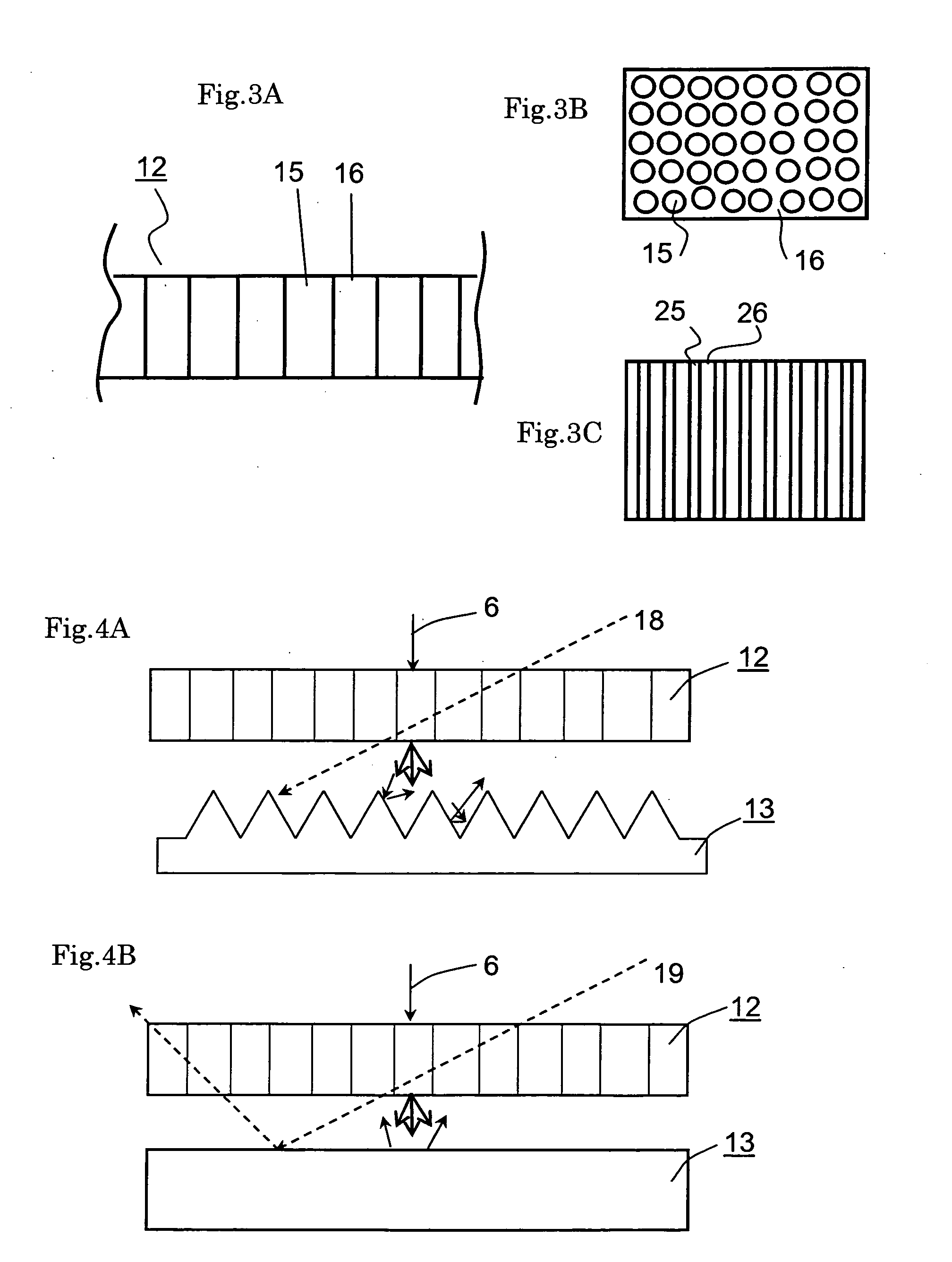
[0079]FIG. 7 shows a scheme of the present embodiment of a light-reflecting layer viewed from the side of the directional diffusing layer. As visualized, the reflecting elements 4 of the light-reflecting layer 3 are formed along the up and down direction. Thus, the reflecting elements 4 are continuously formed along the vertical direction of the light-reflecting layer. By the utilization of such reflecting elements, the same screen with a wide viewing angle in the left and right direction can be realized. FIG. 7 shows a construction, in which there is a spatial distance between the reflecting elements 4. Various other positive and negative relief structures can be utilized as reflecting elements 4 as long as a scattering and reflecting surface is formed.

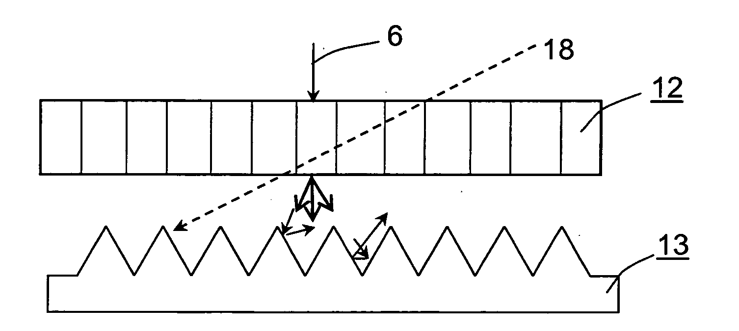
[0080]In FIG. 8, the cross-sectional view of the reflecting elements along the horizontal plane of FIG. 7 is shown. FIG. 8A shows a structure with inward V-shaped relief structure, in which there is a spatial...

third embodiment

of Light-Reflecting Layer

[0084]As described above, the range of reflection angle can be controlled by the structure and positioning pattern of the reflecting elements.

[0085]In the present examples, a consequent application for structuring of the above said is described.

[0086]A case is described in detail, in which the light-reflecting layer is constructed such that also a certain scattering occurs in the up and down direction.

[0087]This means, multiple types of reflecting elements with different scattering and reflection properties are utilized.

[0088]Thereby, a precise control of the proportion of scattered light in the up and down direction versus in the left and right direction is possible and the spatial range of the reflection angle of the screen can be freely designed.

[0089]In FIG. 9, a scheme is shown, in which multiples types of reflecting elements are formed on the light-reflecting layer, in which the scattering and reflection properties of the reflecting elements of type-I ...


PUM


Abstract

A front screen with a simple construction provides a wide viewing angle towards the desired direction, realization of an image projection system. The front screen that is utilized in present invention comprising a directional diffusing layer that transmits and diffuses incoming light from a specified angular range and linearly transmits incoming light from other angles, and a light-reflection layer that provides reflecting elements that scatters and reflects light. Furthermore, the light-scattering field of the reflecting elements in the light-reflecting layer in the up and down direction differs to that in the left and right direction and provides an anisotropic scattering property. Thereby, the construction is adjusted to the viewing condition.

Description

BACKGROUND OF THE INVENTION[0001]1. Field of the Invention[0002]The present invention is related to front screens, on which optical images from high brightness CRT or LCD projectors are displayed as well as a to projection systems utilizing aforementioned screen.[0003]2. Description of the Related Art[0004]Optical image projection systems that utilizes high brightness CRT or LCD projection systems found various applications because of large images with high resolution can be displayed simply and, therefore, can be applied as communication tools for a large number of users.[0005]In recent times, the need for screens that provide a good visible image under bright conditions has emerged.[0006]To minimize the effect of ambient light for the observer, embodiments are known that utilize directional diffusing sheets that transmits and diffuses incoming light from a specific angular range and linearly transmits incoming light from other directions, together with a prism sheet with saw-blade...

Claims


Application Information

Patent Timeline
Patent Type & Authority Applications(United States)
IPC IPC(8): G03B21/60G03B21/00G03B21/14
CPCG03B21/60
Inventor YAMAUCHI, NAOFUMI
Owner YAMAUCHI NAOFUMI
Why Eureka
Try Eureka