Power Converting Apparatus For System Connection
a technology of power conversion apparatus and system connection, which is applied in the direction of electric variable regulation, process and machine control, instruments, etc., can solve the problems of high voltage accumulation in stray capacitance, easy break operation of leakage breaker, and increase in leakage current accordingly, and achieve high power conversion efficiency
- Summary
- Abstract
- Description
- Claims
- Application Information
AI Technical Summary
Benefits of technology
Problems solved by technology
Method used
Image

Examples
first embodiment
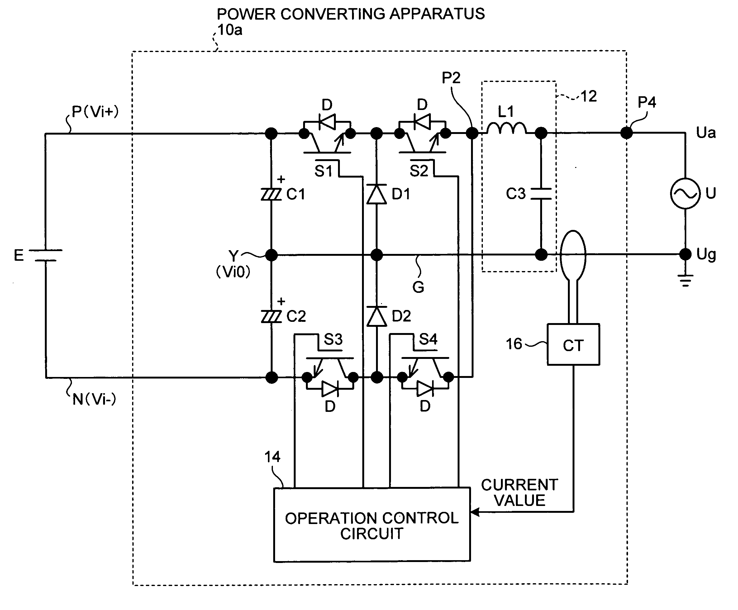
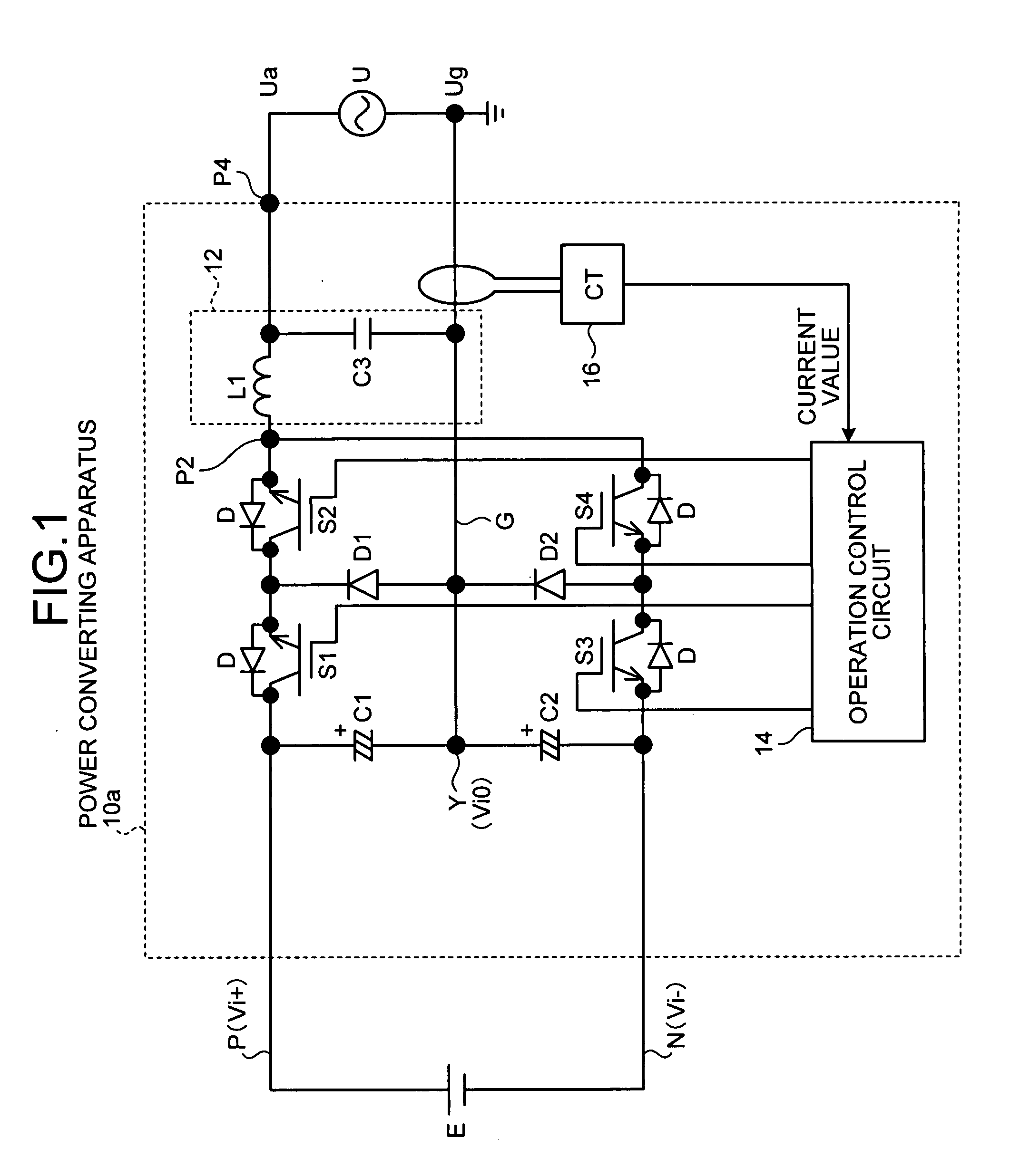
[0067]FIG. 1 is a block diagram of a configuration of a power converting apparatus for system connection according to a first embodiment of the present invention. The power converting apparatus for system connection is hereinafter simply abbreviated as a “power converting apparatus”.
[0068]In FIG. 1, the direct-current power source E is a power generation facility that has a possibility of generating a variation in direct-current power generated. The direct-current power source E includes a fuel cell in addition to a solar cell that receives the influence of sunshine, temperature, and humidity. The direct-current power source E also includes a power generation facility that can output direct-current power by applying a converter to an alternate-current power generator such as wind power generator and a geothermal power generator.
[0069]The system power source U is a commercial power system having a single-phase grounding. This commercial power system employs a system in which the grou...
second embodiment
[0091]FIG. 4 is a block diagram of a configuration of a power converting apparatus for system connection according to a second embodiment of the present invention. In FIG. 4, constituent elements identical with or equivalent to those shown in FIG. 1 (the first embodiment) are denoted with like reference numerals. Parts that are relevant to the second embodiment are mainly explained below.
[0092]As shown in FIG. 4, a power converting apparatus 10b according to the second embodiment includes a resistor R that is present in the grounding wire G, and a voltage detector 22 that detects a drop voltage in the resistor R, in place of the CT 16 in the configuration shown in FIG. 1 (the first embodiment). A voltage detected by the voltage detector 22 is input to an operation control circuit 20 having a different reference numeral.
[0093]The operation control circuit 20 applies a PWM signal and a binary level signal corresponding to each gate electrode of the four switching elements S1 to S4, th...
third embodiment
[0097]FIG. 5 is a block diagram of a configuration of a power converting apparatus for system connection according to a third embodiment of the present invention. In FIG. 5, constituent elements identical with or equivalent to those shown in FIG. 1 (the first embodiment) are denoted with like reference numerals. Parts that are relevant to the third embodiment are mainly explained below.
[0098]As shown in FIG. 5, a power converting apparatus 10c according to the third embodiment includes voltage detectors 24, 26 that detect terminal voltages of the capacitors C1, C2, in the configuration shown in FIG. 1 (the first embodiment). A voltage detected by each of the voltage detectors 24, 26 is input to an operation control circuit 28 having a different reference numeral.
[0099]The operation control circuit 28 controls the generation of a PWM signal to be applied to each gate electrode of the four switching elements S1 to S4 to make small a difference between the current value detected by the...
PUM
 Abstract
Description
Claims
Application Information
 - R&D Engineer
- R&D Manager
- IP Professional
- Industry Leading Data Capabilities
- Powerful AI technology
- Patent DNA Extraction
Browse by: Latest US Patents, China's latest patents, Technical Efficacy Thesaurus, Application Domain, Technology Topic.
© 2024 PatSnap. All rights reserved.Legal|Privacy policy|Modern Slavery Act Transparency Statement|Sitemap