Exhaust casing hub comprising stress-distributing ribs

Active Publication Date: 2008-12-18
SN DETUDE & DE CONSTR DE MOTEURS DAVIATION S N E C M A
6 Cites 18 Cited by

AI-Extracted Technical Summary

Problems solved by technology

However, the currently known casings have a limited life as a result of concentrations of stresses in the cuffs of the hub.
This meas...

Benefits of technology

[0005]The subject of the present invention is an exhaust casing hub and an exhaust casing which overcom...

Abstract

An exhaust casing hub comprises a hub center (6), and an upstream flange (8) and a downstream flange (10) arranged on either side of the hub center. Each flange is terminated by a rim (12). A plurality of cuffs (14) are arranged on the hub center (6) so as to form an angle from the tangent toward the radial direction of 10° to 80°, preferably 15° to 75°. At least one rib is formed at the base of each cuff (14) below a critical stress region (26) in the cuff. The rib is joined to the downstream flange by a downstream end and to the upstream flange by an upstream end.

Application Domain

Engine manufactureEngine fuctions +8

Technology Topic

Critical stressFlange +1

Image

  • Exhaust casing hub comprising stress-distributing ribs
  • Exhaust casing hub comprising stress-distributing ribs
  • Exhaust casing hub comprising stress-distributing ribs

Examples

  • Experimental program(1)

Example

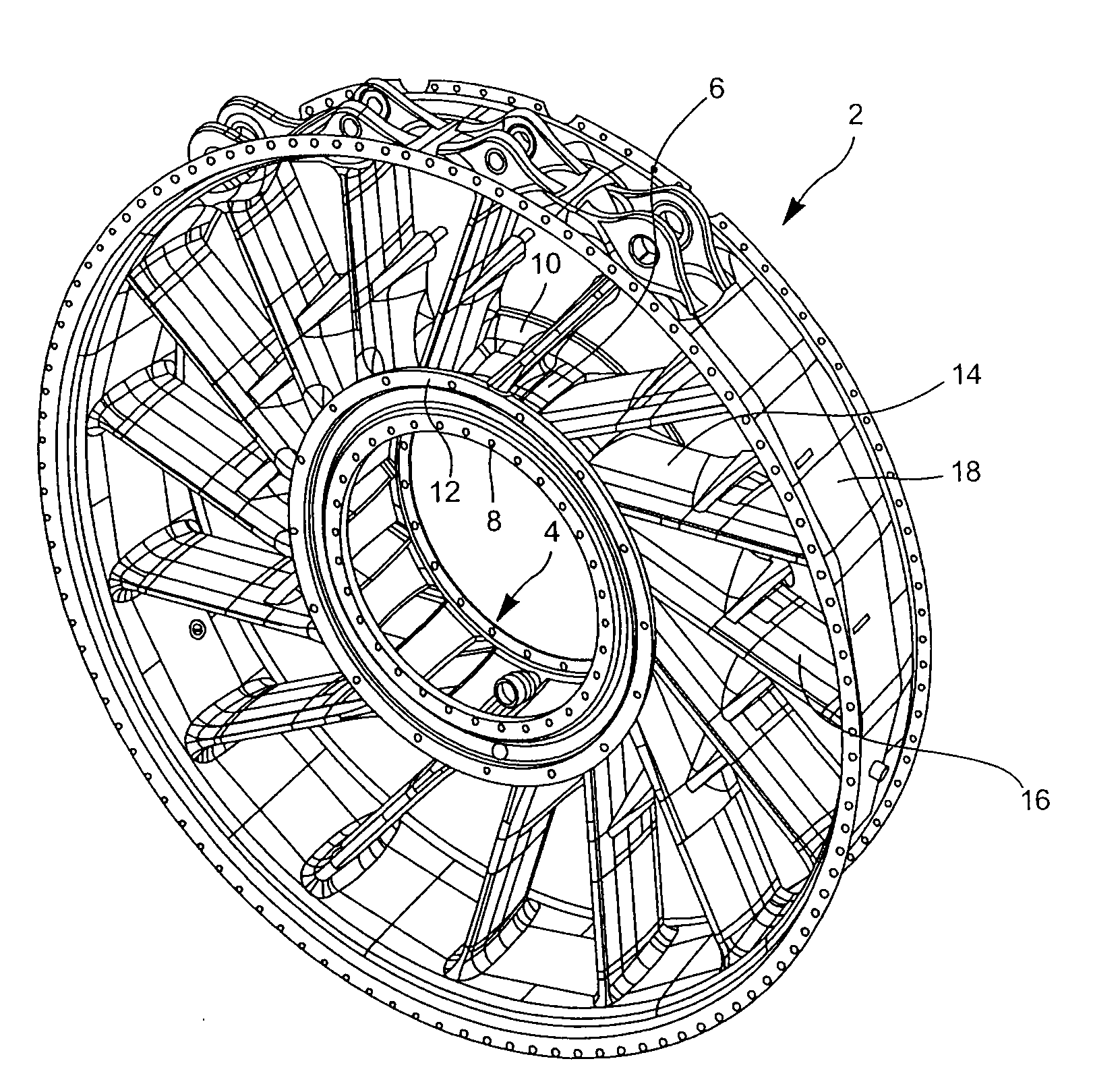
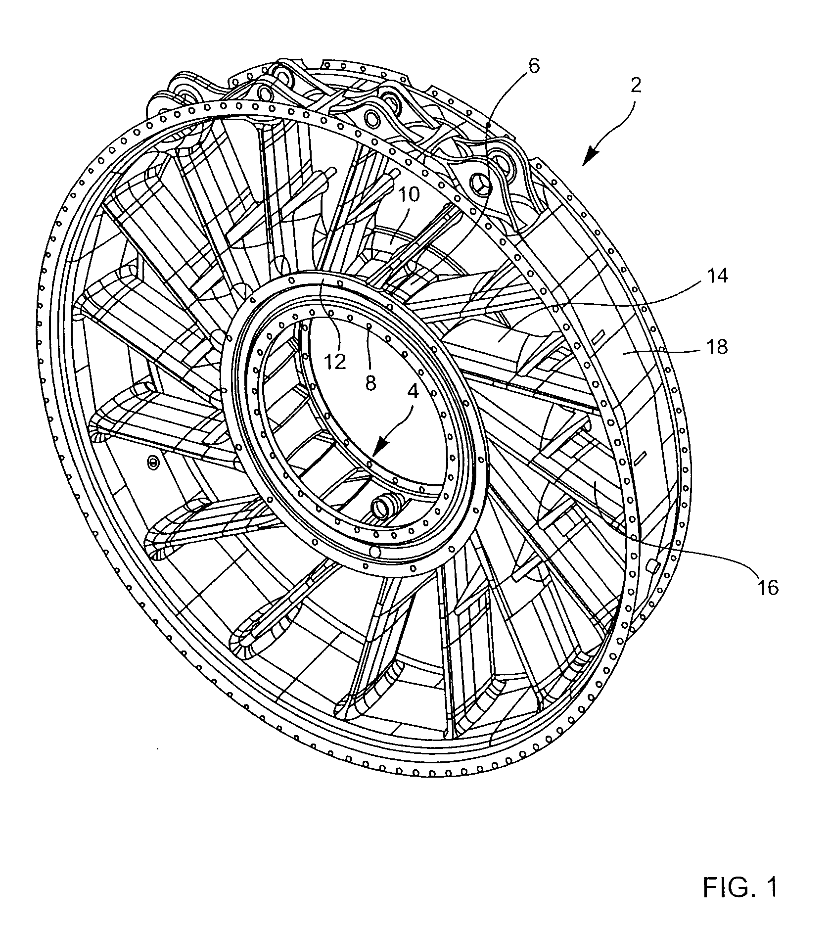
[0016]In FIG. 1, the general reference 2 designates an exhaust casing in accordance with the present invention. This exhaust casing comprises a hub designated by the reference 4. The hub 4 comprises a hub center 6 and, on either side of this hub center 6, an upstream flange 8 and a downstream flange 10 which are terminated by a rim 12. Cuffs 14 are formed on the hub center 6. In the exemplary embodiment represented, the number of these cuffs is sixteen. The hub 4 is a casting. An arm 16 is welded to the end of each of the cuffs 14. There are thus sixteen arms in the exemplary embodiment represented. The circular parts 18, equal in number to the number of arms, are welded to the ends of the arms 16 so as to form a circular shroud which completes the exhaust casing.
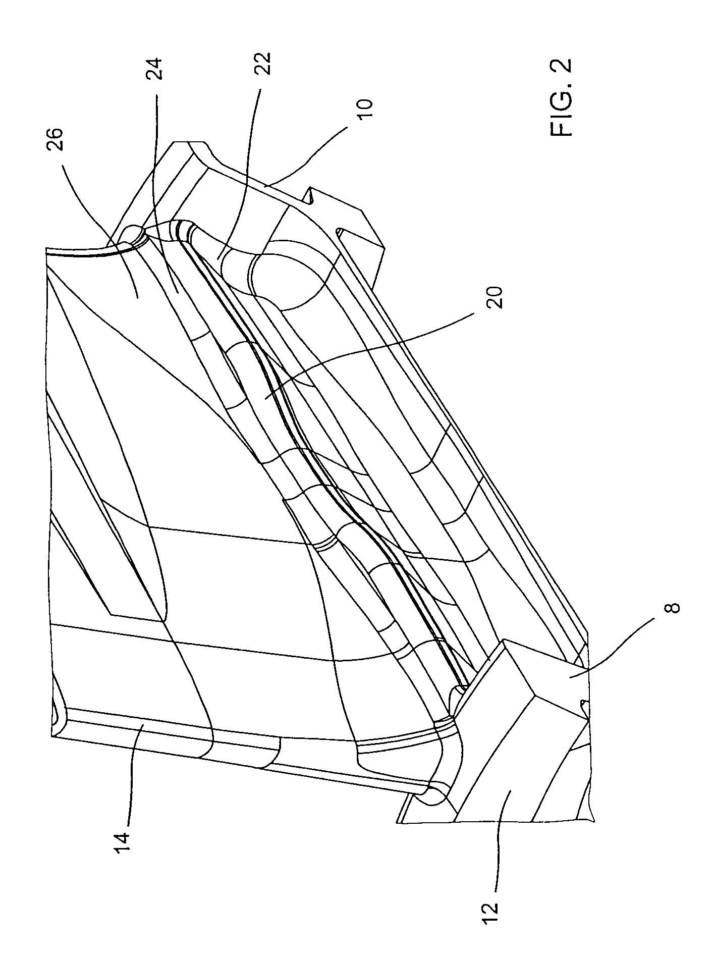
[0017]FIGS. 2 and 3 show a top view and a side view, respectively, of a rib 20 formed in the hub of the exhaust casing represented in FIG. 1. The rib 20 extends from the upstream flange 8 to the downstream flange 10. It is joined to the upstream flange 8 and to the downstream flange 10 by fillets 22. In the same way, it is joined to the cuffs 14 by a fillet 24. Across its height, this rib is placed substantially below the point of maximum stresses 26. Calculations have made it possible to show that the stresses are very well distributed with this rib. The maximum stress drops to 26 hbar, which means that a life exceeding 50000 cycles is conceivable, this being above the upper value currently adopted.
[0018]FIG. 4 shows a front view of a double rib forming part of an exhaust casing in accordance with the present invention.
[0019]The reference 30 designates an upstream rib joined to the upstream flange 8 by a joining radius 32. The reference 34 designates a downstream rib joined to the downstream flange 10 by a joining radius 36. Likewise, the upstream rib 30 joins to the cuff 14 by a joining radius 38, while the downstream rib 34 joins to the cuff 14 by a joining radius 40. Across their height, the ribs 30 and 34 are situated below a region 26 of critical stresses in the cuff 14.
[0020]Measurements have made it possible to show that the stresses are also very well distributed with these two ribs. The maximum stress drops to 31.5 hbar, which means that a life exceeding 36000 cycles is conceivable, this being above the upper value currently adopted.

PUM

no PUM

Description & Claims & Application Information

We can also present the details of the Description, Claims and Application information to help users get a comprehensive understanding of the technical details of the patent, such as background art, summary of invention, brief description of drawings, description of embodiments, and other original content. On the other hand, users can also determine the specific scope of protection of the technology through the list of claims; as well as understand the changes in the life cycle of the technology with the presentation of the patent timeline. Login to view more.

Similar technology patents

Coronary sinus medical electrical lead

InactiveUS20160114155A1current to decreaseincrease life
Owner:MEDTRONIC INC

Fluid pumping apparatus

InactiveUS20030017060A1reduce radial loadincrease life
Owner:THOMAS IND INC

Boiler tube reinforcement device and boiler tube reinforcement method

InactiveUS20200240627A1minimize forceincrease life
Owner:THE CHUGOKU ELECTRIC POWER CO INC

Boiler tube reinforcement device and boiler tube reinforcement method

InactiveUS20180252406A1minimize thermal stressincrease life
Owner:THE CHUGOKU ELECTRIC POWER CO INC

Ice maker having fan assembly and fan assembly control method

ActiveUS20060010900A1increase life
Owner:LG ELECTRONICS INC

Classification and recommendation of technical efficacy words

  • increase life

Top stabilized photochromic lens system

InactiveUS6547390B1increase life
Owner:EXXENE CORP

Method and apparatus for constructing synchronous sensor network

ActiveUS20100118737A1increase life
Owner:ELECTRONICS & TELECOMM RES INST

Internal shock absorber plunger

ActiveUS20060124292A1increase lifeexcellent resistance
Owner:PCS FERGUSON

Organic electroluminescent display device and fabrication method thereof

ActiveUS20080211399A1increase lifeprevent moisture infiltration
Owner:INNOLUX CORP

Deck mop with scrubber

InactiveUS6836921B1increase lifeeffective and easy to use
Owner:QUICKIE MFG
Why Eureka
Try Eureka