Method for the Operation of a Measurement System With a Scanning Probe Microscope and a Measurement System

a scanning probe microscope and measurement system technology, applied in scanning probe microscopy, instruments, nanotechnology, etc., can solve the problems of difficult orientation for the inability to detect the larger area of the measurement sample to be examined, and inability to achieve the intended congruence between the two images. , to achieve the effect of facilitating the precise positioning of the measurement prob

Active Publication Date: 2008-12-18
JPK INSTR +1
View PDF4 Cites 12 Cited by
  • Summary
  • Abstract
  • Description
  • Claims
  • Application Information

AI Technical Summary

Benefits of technology

[0009]The object of the invention is to provide an improved method for the operation of a measurement system with a scanning probe microscope as well as a measurement system with a scanning probe microscope, with which an exact positioning of the measurement probe is facilitated relative to a measurement sample to be examined.

Problems solved by technology

In this way, the intended congruence between both images can be impossible.
Larger areas of the measurement sample to be examined can frequently not be detected without damaging the measurement probe in the process.
However, problems arise here to that extent that the measurement probe normally shadows off a partial sector of the video image, through which an orientation for the positioning of the measurement probe is made very difficult.
In addition, estimating the borders of the video image is just difficult in this way.

Method used


Image

  • Method for the Operation of a Measurement System With a Scanning Probe Microscope and a Measurement System
  • Method for the Operation of a Measurement System With a Scanning Probe Microscope and a Measurement System
  • Method for the Operation of a Measurement System With a Scanning Probe Microscope and a Measurement System

Examples


Embodiment Construction

[0033]The invention is described as follows in greater detail on the basis of embodiment examples with reference to the Figures of a drawing. The Figures show the following:

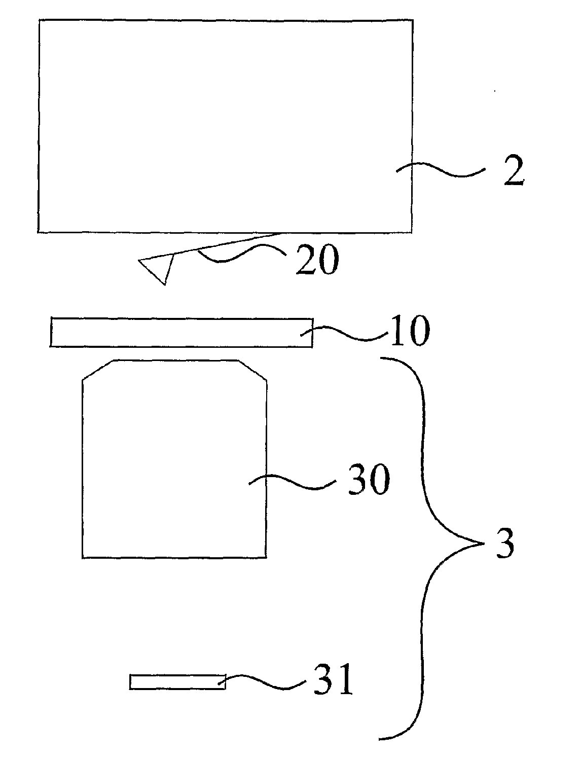
[0034]FIG. 1a schematic illustration of a section of a measurement arrangement;

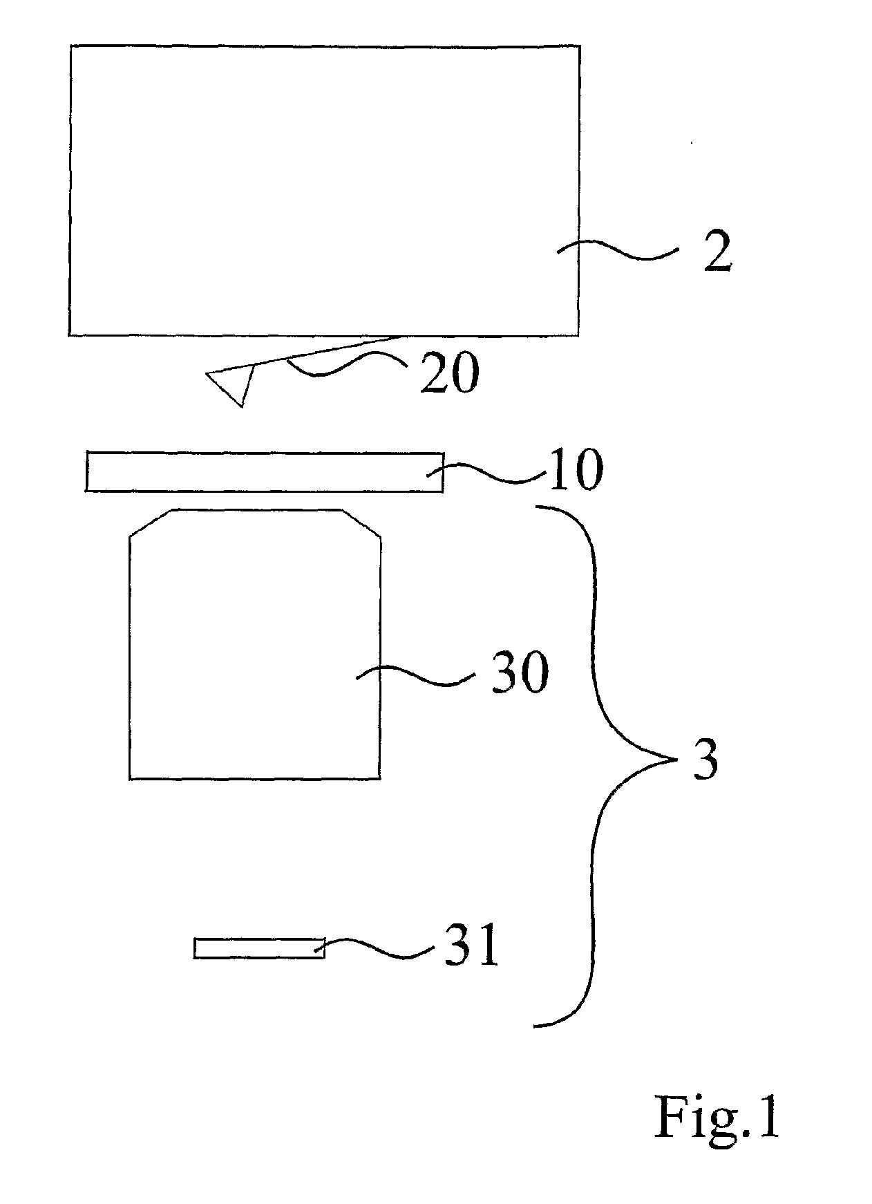
[0035]FIG. 2 a schematic illustration of an equilateral triangle in three different coordinate systems;

[0036]FIG. 3 a schematic illustration for calibrating an angle and an offset in the case of a probe scanner;

[0037]FIG. 4 an optical image of a cantilever with measurement tip and reference point;

[0038]FIG. 5 a further optical image of the cantilever with measurement tip and reference point;

[0039]FIG. 6 another optical image with the cantilever;

[0040]FIG. 7 a sequence diagram and

[0041]FIG. 8 a schematic illustration of a measurement system.

[0042]FIG. 1 shows a schematic illustration of a section of a measurement arrangement with various coordinate systems. A coordinate system Σ1 is assigned to a measurement sample 1 to be examined. A f...


PUM

PropertyMeasurementUnit
scanning probe microscopeaaaaaaaaaa
atomic force microscopeaaaaaaaaaa
optical imageaaaaaaaaaa

Abstract

The invention relates to a method for operating a measurement system containing a scanning probe microscope, in particular an atomic force microscope, and to a measurement system for examining a measurement sample using a scanning probe microscope and for optically examining said sample. In the method, an optical image of a measurement section of a measurement sample to be examined, said image being recorded with the aid of an optical recording device, is displayed on a display apparatus, a choice of a position in the optical image is detected, and, for a scanning probe measurement, a measurement probe which is configured for the scanning probe measurement is moved, using a movement apparatus which moves the measurement probe and the measurement sample relative to one another, to a measurement position, which is assigned to the selected position in the optical image in accordance with coordinate transformation, by virtue of the movement apparatus being controlled in accordance with the coordinate transformation, wherein a previously determined assignment between a coordinate system of the optical image and a coordinate system of a space covered by movement positions of the measurement probe and the measurement sample is formed with the coordinate transformation, wherein the movement positions comprise the measurement position.

Description

[0001]The invention relates to a method for the operation of a measurement system with a scanning probe microscope, particularly an atomic force microscope, as well as a measurement system.BACKGROUND OF THE INVENTION[0002]The scanning probe microscopy (SPM) is a technique where a measurement probe scans a measurement sample to be examined and, in doing so for example, records a topography of the measurement sample. In this context, a relative movement takes place between the measurement probe and the measurement sample which is attained in such a way that at least the measurement probe or at least the measurement sample is moved. Normally, the relative movement is performed as a lateral movement. In addition, a relative movement can also take place in the vertical direction. One form of the scanning probe microscopy is the scanning force microscopy (SFM). With an atomic force microscope used in this case, the measurement probe is formed in the design of a cantilever which carries a ...

Claims


Application Information

Patent Timeline
Patent Type & Authority Applications(United States)
IPC IPC(8): G01N23/00G01Q10/00G01Q30/06G01Q40/00
CPCB82Y35/00G01Q40/00G01Q30/06G01Q10/00G01Q60/00G01Q60/16
Inventor JAHNKE, TORSTENHAGGERTY, MICHAEL RICHARD
Owner JPK INSTR
Why Eureka
Try Eureka