
Segmented Electroluminescent Device for Morphing User Interface

a technology of electroluminescent devices and user interfaces, applied in the field of backlit user interfaces of electronic devices, can solve the problems of increasing the likelihood of user confusion or difficulty in operation of the device, and many mobile devices, including mobile telephones, are getting smaller and thinner

Inactive Publication Date: 2008-12-18
MOTOROLA MOBILITY LLC
View PDF64 Cites 53 Cited by
  • Summary
  • Abstract
  • Description
  • Claims
  • Application Information

AI Technical Summary

Benefits of technology

"The invention is about improving user interfaces on electronic devices by providing multiple user interfaces that can be selected based on the mode of operation. The user interfaces are designed to be easily visible in both low-light and bright-light environments. The invention solves the problem of limited visibility in low-light conditions by using a backlight and a variety of sensors to enable the user interface to be seen in both modes. The technical effects of the invention include improved user experience and better device functionality."

Problems solved by technology

One issue associated with the integration of new features and functionality with devices like mobile telephones involves the user interface.
The problem with this solution is that many mobile devices, including mobile telephones, are getting smaller and thinner.
When many keys are clustered in one location, the likelihood of user confusion or difficulty with operation of the device increases.
A further problem associated with user interfaces involves visibility.

Method used


Image

  • Segmented Electroluminescent Device for Morphing User Interface
  • Segmented Electroluminescent Device for Morphing User Interface
  • Segmented Electroluminescent Device for Morphing User Interface

Examples


Embodiment Construction

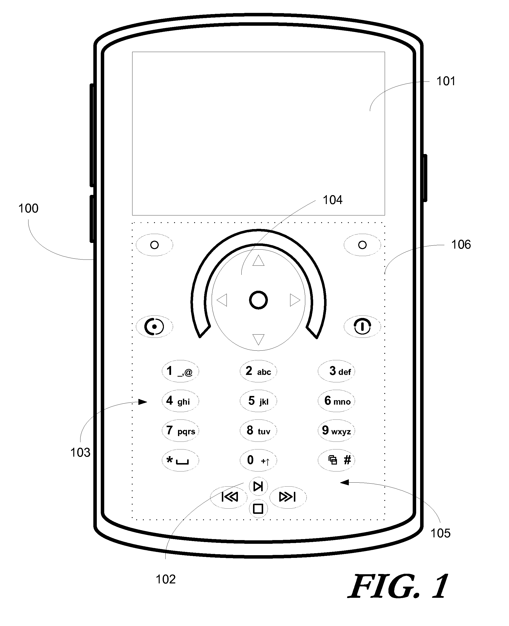
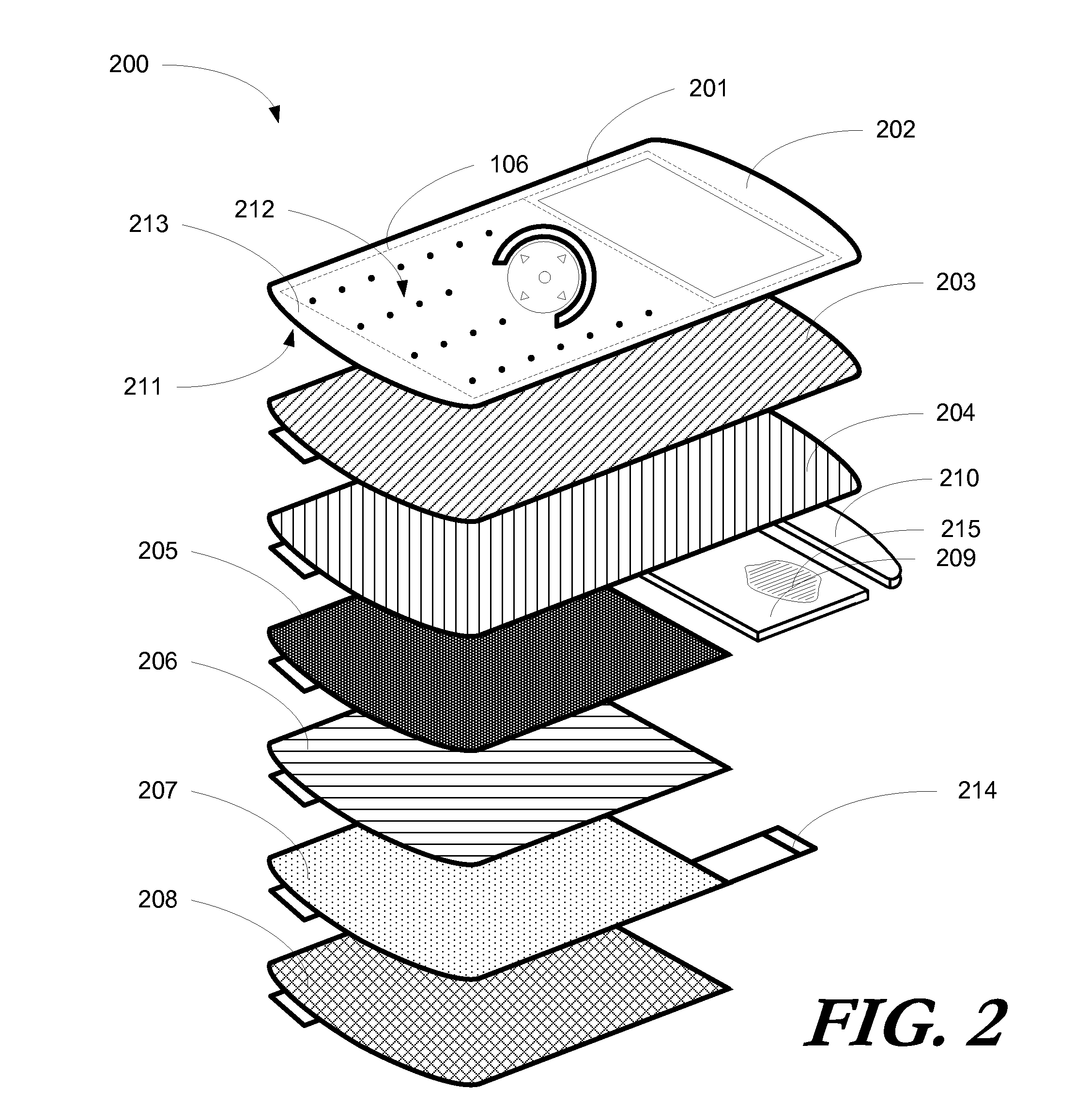
[0028]Embodiments of the invention are now described in detail. Referring to the drawings, like numbers indicate like parts throughout the views. As used in the description herein and throughout the claims, the following terms take the meanings explicitly associated herein, unless the context clearly dictates otherwise: the meaning of “a,”“an,” and “the” includes plural reference, the meaning of “in” includes “in” and “on.” Relational terms such as first and second, top and bottom, and the like may be used solely to distinguish one entity or action from another entity or action without necessarily requiring or implying any actual such relationship or order between such entities or actions. Also, reference designators shown herein in parenthesis indicate components shown in a figure other than the one in discussion. For example, talking about a device (10) while discussing figure A would refer to an element, 10, shown in figure other than figure A.

[0029]It will be appreciated that em...


PUM

PropertyMeasurementUnit
distanceaaaaaaaaaa
electroluminescentaaaaaaaaaa
shapeaaaaaaaaaa

Abstract

A dynamic user interface (1000) is configured to present one of a plurality of keypad configurations to a user. Each keypad configuration includes a plurality of user actuation targets that may be selectively presented to, or hidden from, a user. A segmented optical shutter (204) having segments (801,802,803,804) configured for selective transition from opaque to translucent states is disposed above an segmented optical shutter (204) having a plurality of transparent electrodes (901), each operating as an electroluminescent element. When each segment (801) is active and in a transparent state, a corresponding electroluminescent element is actuated so as to project light (1001,1002) both through the corresponding segment (801) at a first luminosity and about the corresponding segment (801) at a second luminosity, so as to circumscribe the segment (801). The illuminated segment (801) and the circumscription (1004) together form a user actuation target.

Description

BACKGROUND[0001]1. Technical Field[0002]This invention relates generally to electronic devices having user interfaces, and more particularly to an electronic device having a backlit user interface, such as a keypad, that may be selectively configured to present a variety of device-mode-based keypad configurations to a user, where each configuration includes illuminated actuation targets.[0003]2. Background Art[0004]Portable electronic devices, such as radiotelephones, are becoming more and more popular. According to some estimates, over two billion mobile telephones are in use across the world today. As more people come to use mobile devices, designers and engineers are creating devices that integrate more and more features. For instance, many mobile telephones today also include digital camera functions and text messaging functions. Some even include music playback functions.[0005]One issue associated with the integration of new features and functionality with devices like mobile t...

Claims


Application Information

Patent Timeline
Patent Type & Authority Applications(United States)
IPC IPC(8): G09G3/12H04B1/38
CPCG06F1/1626G06F1/1656G06F1/1662G06F1/1684G06F1/169H01H2201/036H01H2219/039H01H2219/054H04M1/22H04M2250/22
Inventor MORALES, JOSEPH M.
Owner MOTOROLA MOBILITY LLC
Learn More