Display device and associated drive control method

a technology of drive control and display device, which is applied in the direction of static indicating devices, instruments, etc., can solve the problems of difficult to achieve and maintain stably light-emitting characteristics, deterioration of display image quality, etc., and achieve the effect of improving display image quality and suppressing occurren

Active Publication Date: 2005-12-22
SOLAS OLED LTD
View PDF6 Cites 71 Cited by
  • Summary
  • Abstract
  • Description
  • Claims
  • Application Information

AI Technical Summary

Benefits of technology

[0025] The present invention features a display device which employs the drive control method of a current application method that supplies gradation current corresponding to the display data to each display pixel constituting a display panel and performs a light emitting operation at a predetermined luminosity gradation. The present invention has the advantages of being able to suppress occurrence of an insufficient write-in state due to the capacity component which is parasitic on the data lines, to perform a light emitting operation of the light emitting devices at the proper luminosity gradation and to achieve improvement of the display image quality.

Problems solved by technology

This presents a problem in that the desired light emitting characteristic (displayed at a predetermined luminosity gradation) is difficult to achieve and maintain stably over a long period of time.
Thus, there is a problem in that proper gradation control cannot be accomplished as variations in the light emitting characteristics of each display pixel are generated which causes deterioration of the display image quality.
However, a light emitting driver circuit that employs the current application method described above has a problem as explained below.
As a result, write-in deficiencies occur due to the inability to fully write-in the display data to each display pixel.
Thus, this situation produces an unmanageable problem in executing a light emitting operation at the appropriate luminosity gradation corresponding to the display data which causes deterioration of the display image quality.

Method used


Image

  • Display device and associated drive control method
  • Display device and associated drive control method
  • Display device and associated drive control method

Examples


1st embodiment

1st Embodiment

[0064]

[0065] Initially, the 1st embodiment of the display device related to the present invention will be explained with reference to the drawings.

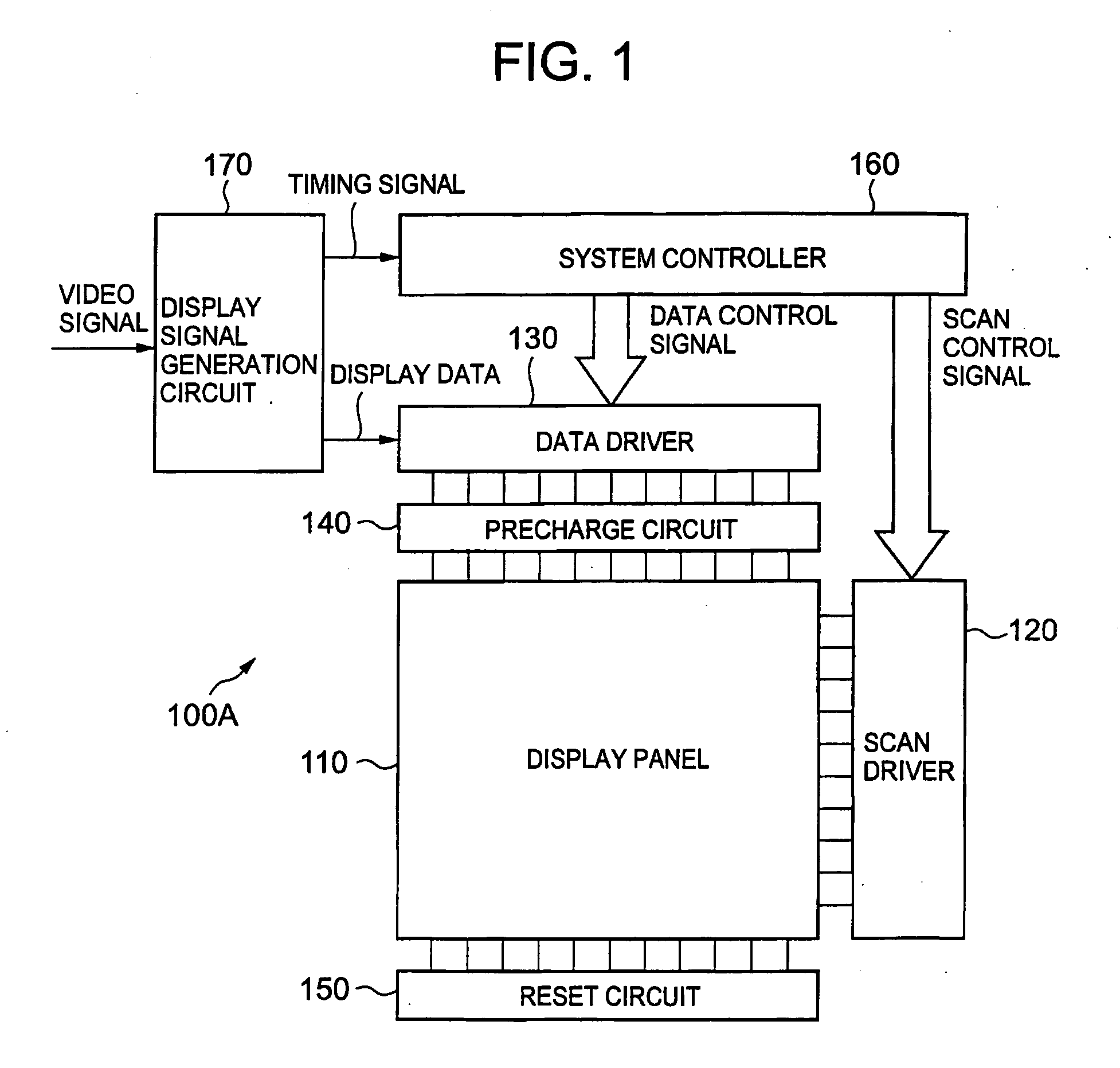
[0066]FIG. 1 is a schematic block diagram showing the 1st embodiment of the display device related to the present invention.

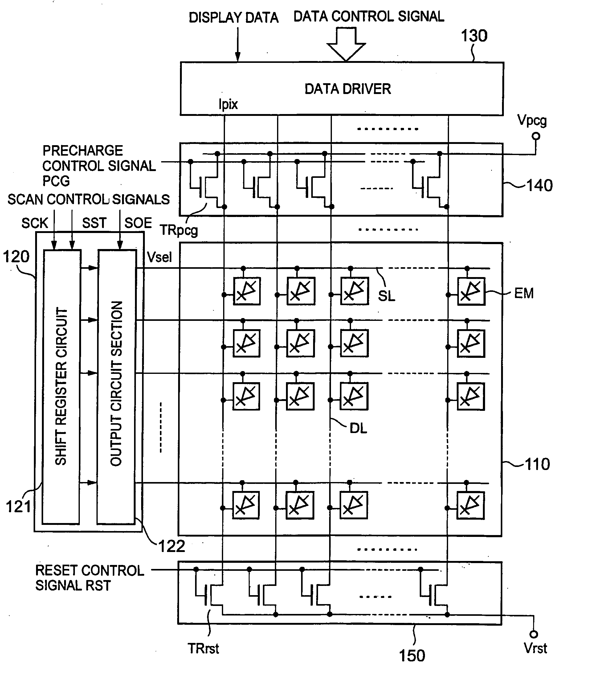
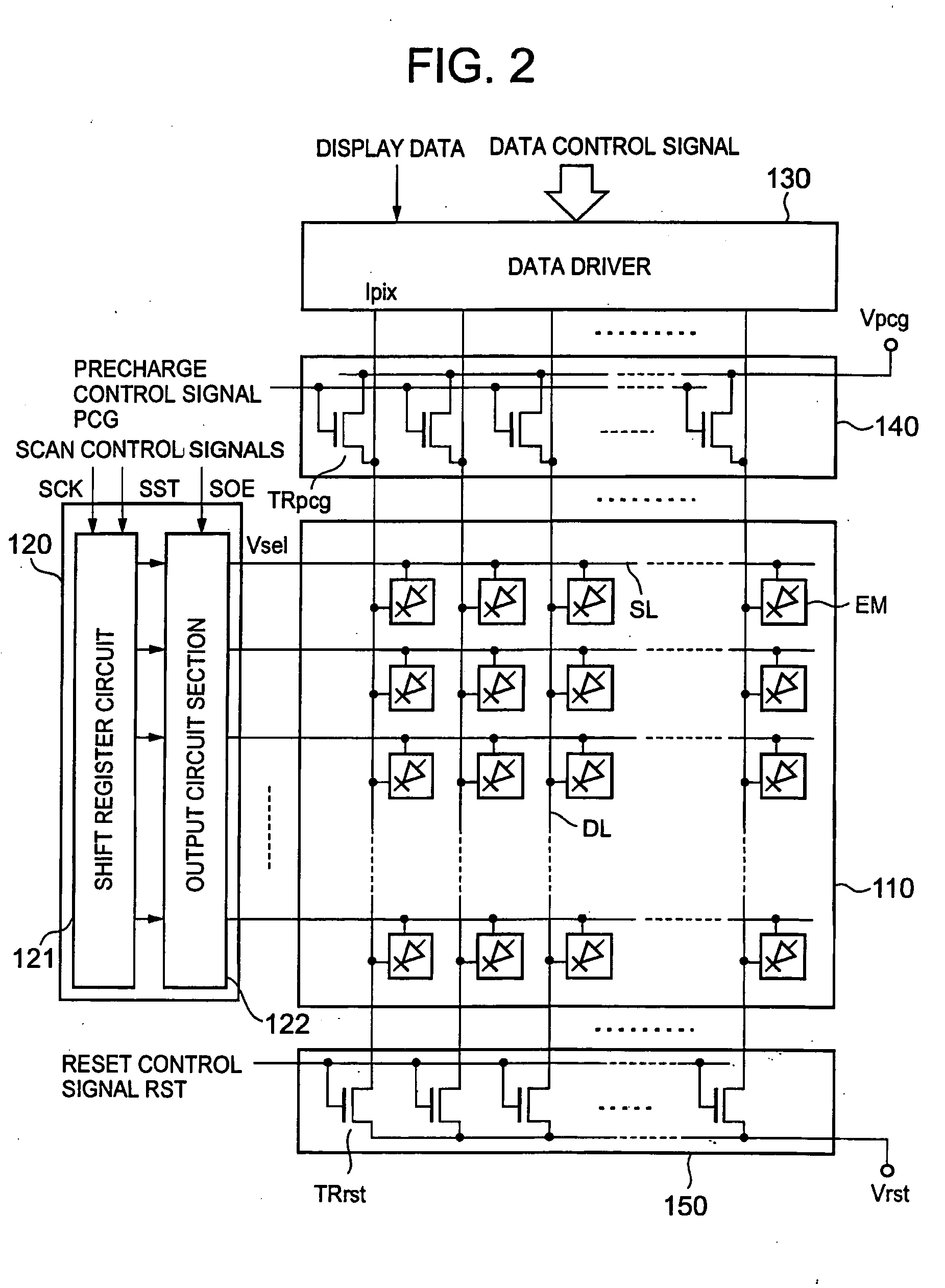
[0067]FIG. 2 is an outline configuration diagram showing the substantial part composition of the display device related to the 1st embodiment.

[0068] Here, concerning any configuration equivalent to the conventional prior art (FIG. 23) mentioned above, the same or equivalent nomenclature is appended.

[0069] As seen in FIG. 1 and FIG. 2, the display device 100A related to this embodiment, in summary, has a configuration comprising a display panel 110, a scan driver 120 (scan driver circuit), a data driver 130 (signal driver circuit), a precharge circuit 140, a reset circuit 150, a system controller 160 (operation control circuit) and a display signal emitting circuit 170. The display panel 110 contains...

2nd embodiment

2nd Embodiment

[0168] Next, the 2nd embodiment of the display device and associated drive control method will be explained with reference to the drawings.

[0169]

[0170]FIG. 15 is a schematic block diagram showing the 2nd embodiment of the display device related to the present invention.

[0171]FIG. 16 is an outline configuration diagram showing the substantial part composition of the display device related to the 2nd embodiment.

[0172] Here, concerning any configuration equivalent to the 1st embodiment mentioned above, the same or equivalent nomenclature is appended and the explanation is simplified or omitted.

[0173] As seen in FIG. 15, the display device 100B related to this embodiment, in summary, has a configuration like the 1st embodiment mentioned above, except the reset circuit 150 is omitted.

[0174] Referring to FIG. 16, the display pixels EM situated in the display panel 110 have a configuration comprising a power supply driver 180. The power supply driver 180 applies the powe...

3rd embodiment

3rd Embodiment

[0200] Next, the 3rd embodiment of the display device and associated drive control method will be explained with reference to the drawings.

[0201] Because the display device related to this embodiment, in summary, has the same configuration as the 1st embodiment (FIG. 1, FIG. 2, FIG. 8) mentioned above, a detailed explanation about each configuration is omitted.

[0202]FIG. 21 is a timing chart showing the 1st example of the drive control method for the display devices related to the 3rd embodiment.

[0203]FIG. 22 is a timing chart showing the 2nd example of the drive control method for the display devices related to the 3rd embodiment.

[0204] Here, the drive control method will be explained while accordingly referring to the configuration of the display device shown in FIG. 8 and the light emitting driver circuit (display pixel) shown in FIG. 5.

[0205] In the drive control method related to the 1st embodiment mentioned above, a method is described in which as a precharg...


PUM


Abstract

A display device which displays image information based on display data comprising a display panel having a plurality of signal lines and scanning lines with a plurality of display pixels containing current control type light emitting devices; a scan driver circuit applies a scanning signal to each of the scanning lines and sets the display pixels connected to the scanning lines in a selective state; a signal driver circuit generates gradation current based on the display data luminosity gradation component and supplies to the display pixels set in the selective state; a precharge circuit applies a precharge voltage to each signal line and sets a capacity component attached to each of the scanning lines in a predetermined charged state; and an operation control circuit controls setting of the light emitting devices in a non-light emitting state when the capacity component is set in a predetermined charged state.

Description

CROSS-REFERENCE TO RELATED APPLICATION [0001] This application is based upon and claims the benefit of priority from the prior Japanese Patent Application No. 2004-181764, filed Jun. 18, 2004, which is entirely in incorporated herein by reference. BACKGROUND OF THE INVENTION [0002] 1. Field of the Invention [0003] The present invention relates to a display device and its associated drive control method. More particularly, the present invention relates to a display device and a drive control method for this display device comprising a display panel constituted with an array of plural display pixels containing current control type light emitting devices for performing a light emitting operation at a predetermined luminosity gradation by supplying current corresponding to the display data. [0004] 2. Description of the Related Art [0005] Conventionally, a light emitting device type display (display device) comprising a display panel consisting of a two-dimensional array of display pixel...

Claims


Application Information

Patent Timeline
Patent Type & Authority Applications(United States)
IPC IPC(8): G09G3/20G09G3/30
CPCG09G3/325G09G3/3266G09G3/3283G09G2300/0819G09G2310/027G09G2300/0866G09G2310/0216G09G2310/0248G09G2310/0251G09G2300/0842G09G3/20G09G3/30
Inventor TAKEI, MANABUSHIRASAKI, TOMOYUKIYAMAGUCHI, IKUHIROOZAKI, TSUYOSHIOGURA, JUN
Owner SOLAS OLED LTD
Why Eureka
Try Eureka