Stacked color photodisplay

a color photodisplay and color technology, applied in the field of stacking color photodisplay, can solve the problems of image deformation with time and lcds have not been popularized

Inactive Publication Date: 2008-12-18
KENT DISPLAY SYST
View PDF99 Cites 31 Cited by
  • Summary
  • Abstract
  • Description
  • Claims
  • Application Information

AI Technical Summary

Benefits of technology

[0022]The photocell display device can incorporate transparent conducting electrodes above and below the photo chiral doped chiral nematic material. The photo display design is similar to a normal bistable electronically switched display; however, the electrodes do not have to be patterned and electronic drive and controller circuitry is not present. The purpose o

Problems solved by technology

It is largely because of these problems that LCDs have not been popular for such applications as point of sales signs in supermarkets, body worn displays such as badges and other applications where either the complexity of wiring up a collection of displays

Method used


Image

  • Stacked color photodisplay
  • Stacked color photodisplay
  • Stacked color photodisplay

Examples


example 1

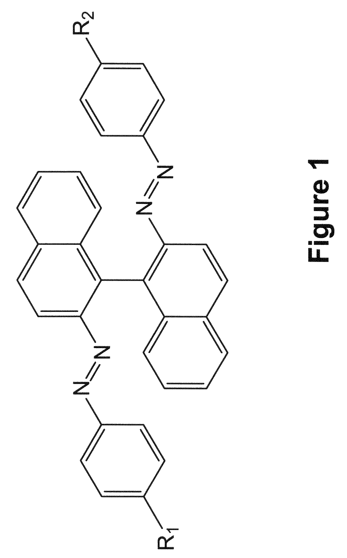
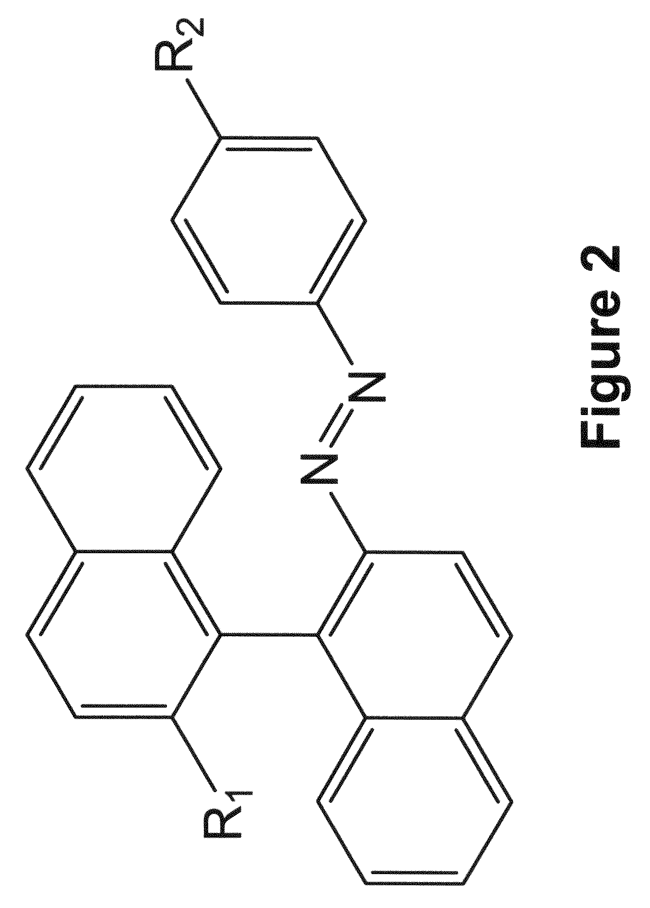
[0138]Reversible photo responsive chiral compounds of the structure diagramed in FIG. 1 with end chains: 3a) R═OC8H17, 3b) R═OC10H21, 3c) R═OC12H25, and 3d) R═OC14H29 respectively were synthesized to explore their physical characteristics for photodisplay applications. In addition reversible photo responsive chiral compounds of the structure diagramed in FIG. 2 with end chains R═CnH2n+1 (e.g. 4a R═C11H23 and 4b R═C2H5) respectively were also synthesized for comparison.

[0139]The reversible photo responsive chiral compounds were synthesized according to the following scheme.

[0140]Synthesis of the intermediate 2:

[0141](S)-(−)-1,1′-Binaphthyl-2,2′-diamine or (R)-(+)-1,1′-binaphthyl-2,2′-diamine (1.00 g, 3.52 mmol) was dissolved in a solution of H2O (17 mL) and concentrated HCl (2.5 mL). The solution was cooled to 0° C. at ice water bath. A solution of sodium nitrite (0.58 g, 8.44 mmol) in H2O (10 mL) was dropped at ice water bath with stirring. The resulting brown yellow suspension was ...

example 2

[0154]The helical twisting power, HTP, of the compounds 3a-d and 4a,b was measured by dissolving a known quantity of material in a nematic liquid crystal host and measuring the induced helical pitch length, in this case, by observing the wavelength of visible light reflected from the Bragg reflective material. The nematic host was E7, a eutectic mixture of liquid crystal components commercially available from Merck. The chiral material to be investigated was dissolved in the nematic host in sufficient quantity to form a chiral nematic material that was Bragg reflective in the visible spectrum. The HTP was measured in a display cell fabricated from two glass substrates (2 in×2 in) each coated with a transparent conductor indium tin oxide (ITO), which was over-coated with a hard coat layer and a polyimide alignment layer. The two glass pieces are held together with a gasket material and spacers to maintain a cell thickness of 5 microns. The back surface of the cell, opposite the viewi...

example 3

[0155]A fixed negative photo image was created on a display cell. The display cell was fabricated from of two glass substrates (2 in×2 in) each coated with a transparent conductor indium tin oxide (ITO), which was overcoated with a hard coat layer and a polyimide alignment layer. The two glass pieces are held together with a gasket material and spacers to maintain a cell thickness of 5 microns. A small gap is left in the gasket material to fill the cell with the photochiral liquid crystal mixture. The cell is filled in a vacuum chamber with cholesteric liquid crystal mixture consisting of 0.8% 3b (left-handed photo-chiral dopant), 15.87% E44 (nematic host, Merck), and 83.33% BLO61 (mixture of a nematic host with right-handed chiral dopant, Merck). Once filled, the cell is placed in a bladder press at 6 psi for 30 minutes to press the cell to a uniform thickness. After 30 minutes, the cell is sealed with Hardman's two-part epoxy. Once the epoxy is cured, the cell is back painted with...


PUM


Abstract

The invention comprises a stacked color photodisplay apparatus using a photosensitive cholesteric liquid crystalline material on which an image can be optically addressed, retained without degradation for an indefinite period of time, electrically erased and a new image addressed. This is similar to a photographic film except that the photodisplay film can be used over and over again similar to digital display but without the cost of addressing electronics. Included is a device for enhancing the brightness of the image and electrooptical devices for optically writing digital images on the photodisplay. Each cell in the stack can be selectively addressed with a different optical image such as the red, green and blue components of a color digital image.

Description

CROSS-REFERENCE TO RELATED APPLICATION[0001]This is a continuation-in-part of pending U.S. patent application Ser. No. 11 / 762,174 filed Jun. 13, 2007, which is a continuation-in-part of U.S. patent application Ser. No. 11 / 697,514 filed Apr. 6, 2007, which is a continuation-in-part of U.S. patent application Ser. No. 11 / 006,100 filed Dec. 7, 2004, which issued as U.S. Pat. No. 7,236,151 on Jun. 26, 2007, and claims the benefit of U.S. Provisional Patent Application No. 60 / 565,586 filed Apr. 27, 2004 and U.S. Provisional Patent Application No. 60 / 539,873 filed Jan. 28, 2004, all of which are incorporated herein by reference in their entireties.BACKGROUND OF THE INVENTION[0002]A revolution in the information display technology began in the early 1970s with the invention of the liquid crystal display (LCD). Because the LCD is a flat-panel display of light weight and low power which provides a visual read out that conforms to the small size, weight and battery demands of a handheld elect...

Claims


Application Information

Patent Timeline
IPC IPC(8): G02F1/137G09G3/36
CPCG02F1/13475G02F1/13476Y10T428/1005Y10T428/10G02F2001/13478C09K2323/00C09K2323/02G02F1/13478
Inventor DOANE, J. WILLIAMKHAN, ASAD A.MONTBACH, ERICAVENKATARAMAN, NITHYA
Owner KENT DISPLAY SYST
Why Eureka
Try Eureka