Liquid Crystal Display Mounted With IC Tag and Method for Manufacturing the Same

a liquid crystal display and wireless technology, applied in the field of liquid crystal displays, can solve the problems of inability to read data from the intensity of the radio wave from the antenna fluctuating, and the inability to paste the wireless ic tag onto the small-size liquid crystal display, so as to increase the size of the liquid crystal display, enhance the intensity of the radio wave from the antenna, and increase the length of the antenna

Inactive Publication Date: 2008-12-18
HITACHI LTD
View PDF4 Cites 24 Cited by
  • Summary
  • Abstract
  • Description
  • Claims
  • Application Information

AI Technical Summary

Benefits of technology

[0005]In consideration of the aforementioned problems, it is an object of the present invention to provide a liquid crystal display mounted with an IC tag in which information of an IC chip can be read from the surface of the liquid crystal display easily, while the IC chip can be attached to the small-size liquid crystal display without reducing the attraction of design thereof, and a method for manufacturing the liquid crystal display.
[0012]According to the liquid crystal display mounted with an IC tag according to the present invention, the antenna placed out of the region of the image electrodes formed on the glass substrate of the liquid crystal display constitutes a wireless IC tag. Accordingly, an image is disturbed less due to the influence of the antenna on the image electrodes, and transmitted radio waves are disturbed less due to the influence of the image electrodes on the antenna. Further, unlike the related art, the antenna length is not restricted by the region of the image electrodes as is in the related art, but the antenna length can be increased. It is therefore possible to enhance the intensity of radio waves from the antenna. In addition, the antenna is formed to be out of the region of the image electrodes, that is, outside the region of available pixels. Accordingly, there is no fear that the size of the liquid crystal display increases. Consequently, it is possible to secure the miniaturization of a portable telephone or the like.

Problems solved by technology

It is therefore considerably difficult to paste the wireless IC tag onto a small-size liquid crystal display.
Accordingly, there is a fear that the intensity of a radio wave from the antenna fluctuates because a driving voltage is selectively applied or not applied to the matrix-shaped transparent electrodes.
That is, in some display conditions of the liquid crystal display, data cannot be read from the wireless IC tag.
As a result, the miniaturization of a portable telephone or the like is hindered, and there is a fear that the attraction on design of the portable telephone is spoilt.
In addition, when the antenna is pasted onto the back side of the liquid crystal display, the intensity of a radio wave radiated to the surface side is weakened.
Thus, the user-friendliness deteriorates.

Method used


Image

  • Liquid Crystal Display Mounted With IC Tag and Method for Manufacturing the Same
  • Liquid Crystal Display Mounted With IC Tag and Method for Manufacturing the Same
  • Liquid Crystal Display Mounted With IC Tag and Method for Manufacturing the Same

Examples


embodiment 1

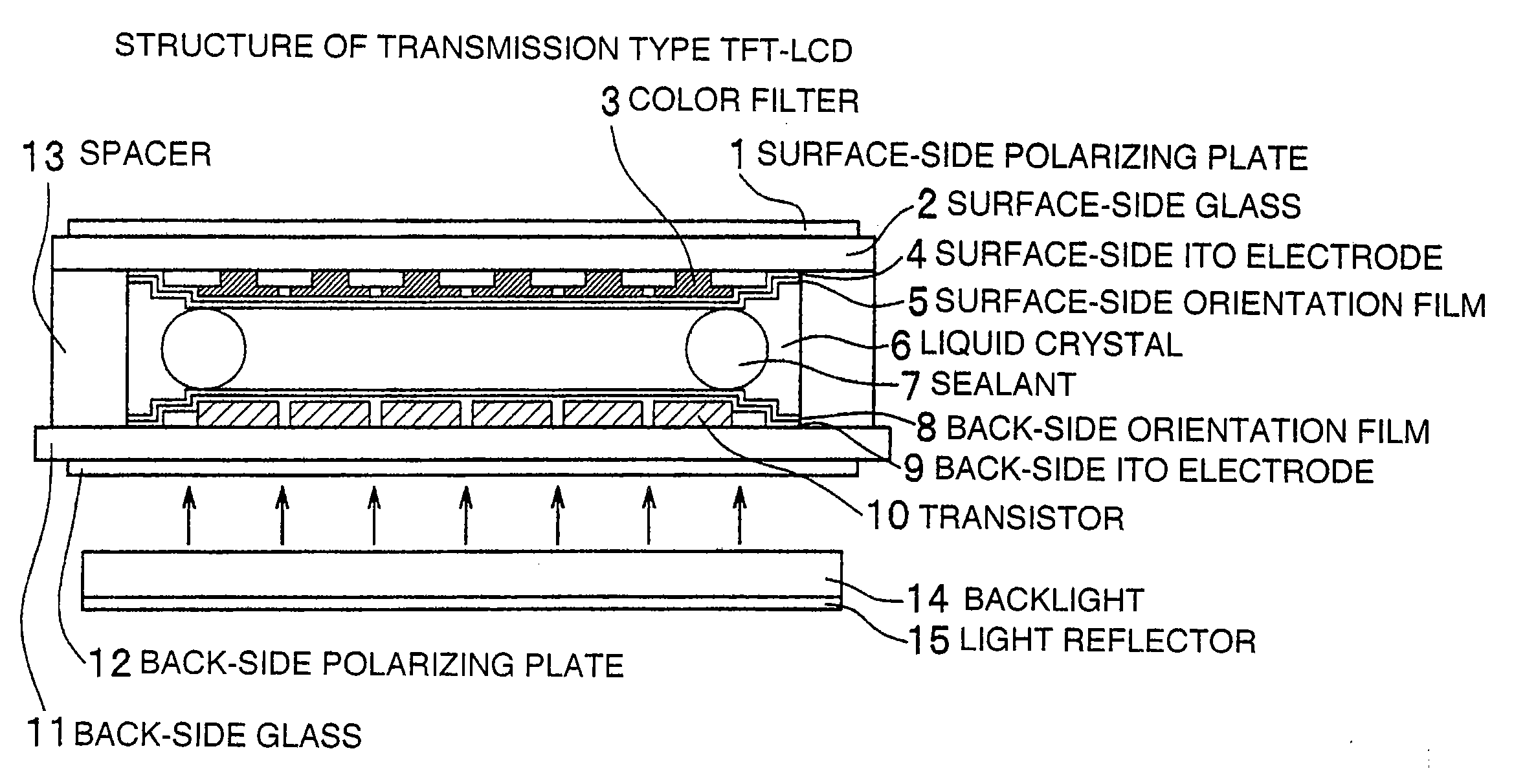
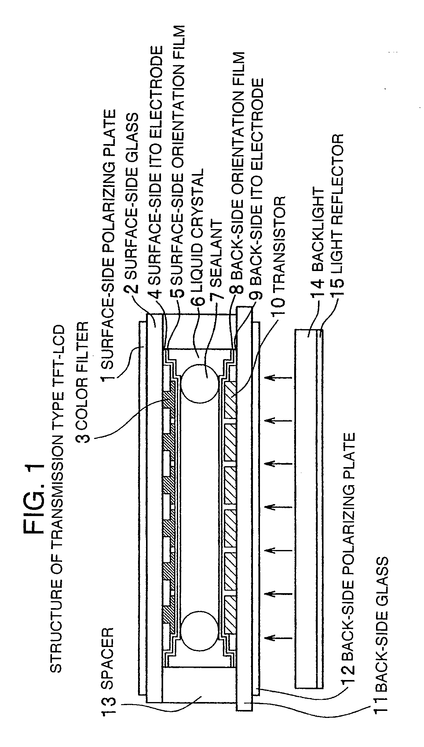
[0040]In Embodiment 1, description will be made about a method for mounting a wireless IC tag, in which an antenna and a wireless IC tag are mounted on an active matrix type liquid crystal display having X-axis electrodes and Y-axis electrodes formed only in a lower electrode layer in a transmission type TFT-LCD shown in FIG. 1. Embodiment 1 has some variations as to the position where the antenna is formed. Of the variations, typical variations will be described.

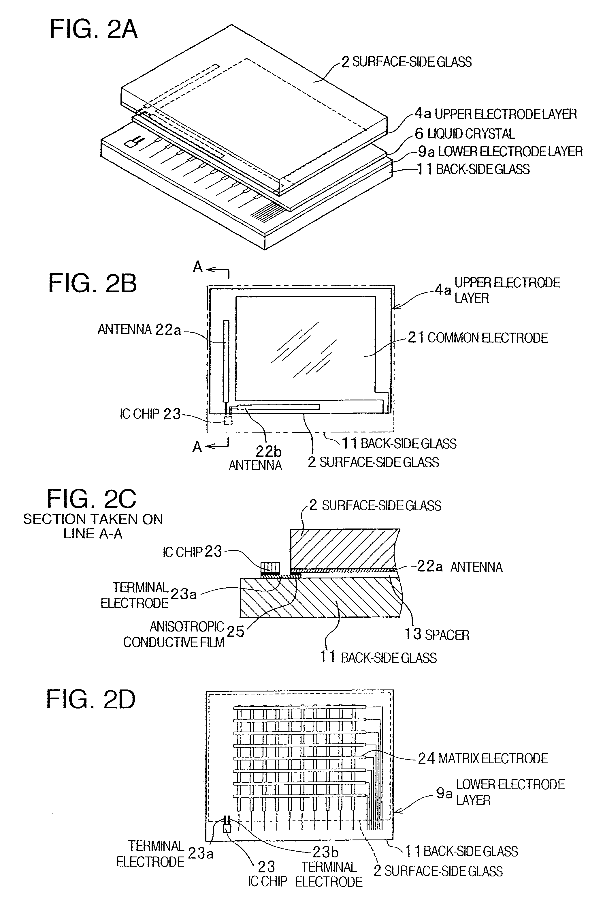
[0041]First, description will be made about Variation 1 of Embodiment 1 in which a wireless IC tag is mounted on an active matrix type liquid crystal display. FIGS. 2A-2D are conceptual diagrams of Variation 1 in Embodiment 1 of the present invention in which a wireless IC tag is mounted on an active matrix type liquid crystal display. FIG. 2A shows a laminated configuration of the liquid crystal display. FIG. 2B shows an upper electrode layer. FIG. 2C shows a partial section taken on line A-A in FIG. 2B. FIG. 2D shows a lo...

embodiment 2

[0067]In Embodiment 2, description will be made about a method for mounting a wireless IC tag, in which each antenna and an IC chip are mounted on a passive matrix type liquid crystal display having X-axis electrodes formed in an upper electrode layer and Y-axis electrodes formed in a lower electrode layer. Embodiment 2 also has some variations as to the position where the antenna is formed. Of the variations, typical variations will be described here.

[0068]First, description will be made about Variation 1 of Embodiment 2 in which a wireless IC tag is mounted on a passive matrix type liquid crystal display. FIGS. 11A-11D are conceptual diagrams of Variation 1 in Embodiment 2 of the present invention in which a wireless IC tag is mounted on a passive matrix type liquid crystal display. FIG. 11A shows a laminated configuration of the liquid crystal display. FIG. 11B shows an upper electrode layer. FIG. 11C shows a partial section taken on line B-B in FIG. 11B. FIG. 11D shows a lower e...

embodiment 3

[0076]Next, description will be made about Embodiment 3 in which a wireless IC tag is mounted on a liquid crystal display having a light reflector. FIGS. 15A-15B are conceptual diagrams showing Embodiment 3 of the present invention in which a wireless IC tag is mounted on a liquid crystal display having a light reflector. FIG. 15A shows a sectional view of the liquid crystal display, and FIG. 15B shows a plan view of the liquid crystal display. As shown in FIG. 15A, the liquid crystal display has a laminated configuration of a surface-side glass 2, an upper electrode layer 4a, a liquid crystal 6, a lower electrode layer 9a, a back-side glass 11 and a light reflector 33. In the liquid crystal display configured thus, as shown in FIG. 15B, an antenna 22 is connected to one terminal of an IC chip 23, while the light reflector 33 is connected to the other terminal of the IC chip 23 so that the light reflector 33 can serve as a radiation surface of the antenna. In this case, it is desire...


PUM

PropertyMeasurementUnit
depthaaaaaaaaaa
widthaaaaaaaaaa
anisotropic conductiveaaaaaaaaaa

Abstract

A liquid crystal display with an IC tag in which information of an IC chip can be read from the surface of the liquid crystal display, while the IC chip can be mounted on the small-size liquid crystal display without lowering the attraction of design thereof. A common electrode is formed in a wide region of an upper electrode layer constituting the liquid crystal display. Antennas are formed in a region of an edge portion of the upper electrode layer where the common electrode is not formed, and within the region of a surface-side glass. An IC chip is placed out of the region of the surface-side glass. X-axis and Y-axis matrix electrodes are formed in a region of a lower electrode layer opposite to the common electrode.

Description

CROSS-REFERENCES TO RELATED APPLICATIONS[0001]This application is a continuation of U.S. application Ser. No. 11 / 007,901, filed Dec. 8, 2004, which claims priority from Japanese Application No. 2004-233460, filed Aug. 10, 2004, all of which are herein incorporated by reference for all purposes.BACKGROUND OF THE INVENTION[0002]The present invention relates to a liquid crystal display mounted with a wireless IC tag for transmitting information stored in an IC chip from an antenna wirelessly, and a method for manufacturing the same.RELATED ART[0003]In recent years, a wireless IC tag is attached to a liquid crystal display of a portable telephone or the like so that unique information of the portable telephone or the like can be read in a non-contact manner by a reader or the like. Such a wireless IC tag is constituted by a small IC chip for storing information and an antenna for transmitting the information of the IC chip wirelessly. The IC chip and the antenna are integrally formed in...

Claims


Application Information

Patent Timeline
Patent Type & Authority Applications(United States)
IPC IPC(8): G02F1/13
CPCG02F1/13G02F1/1345
Inventor SAKAMA, ISAOASHIZAWA, MINORU
Owner HITACHI LTD
Why Eureka
Try Eureka