
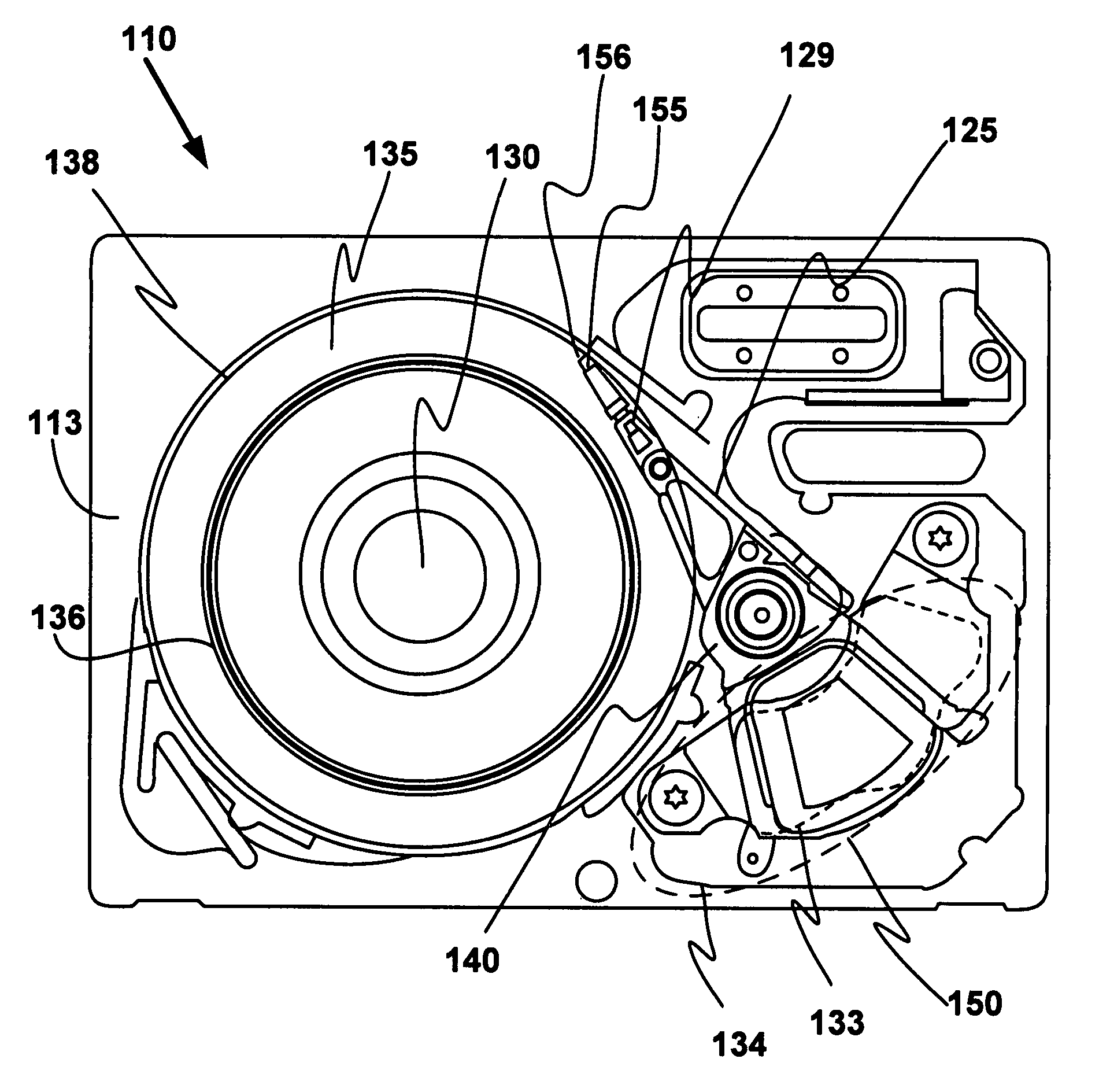
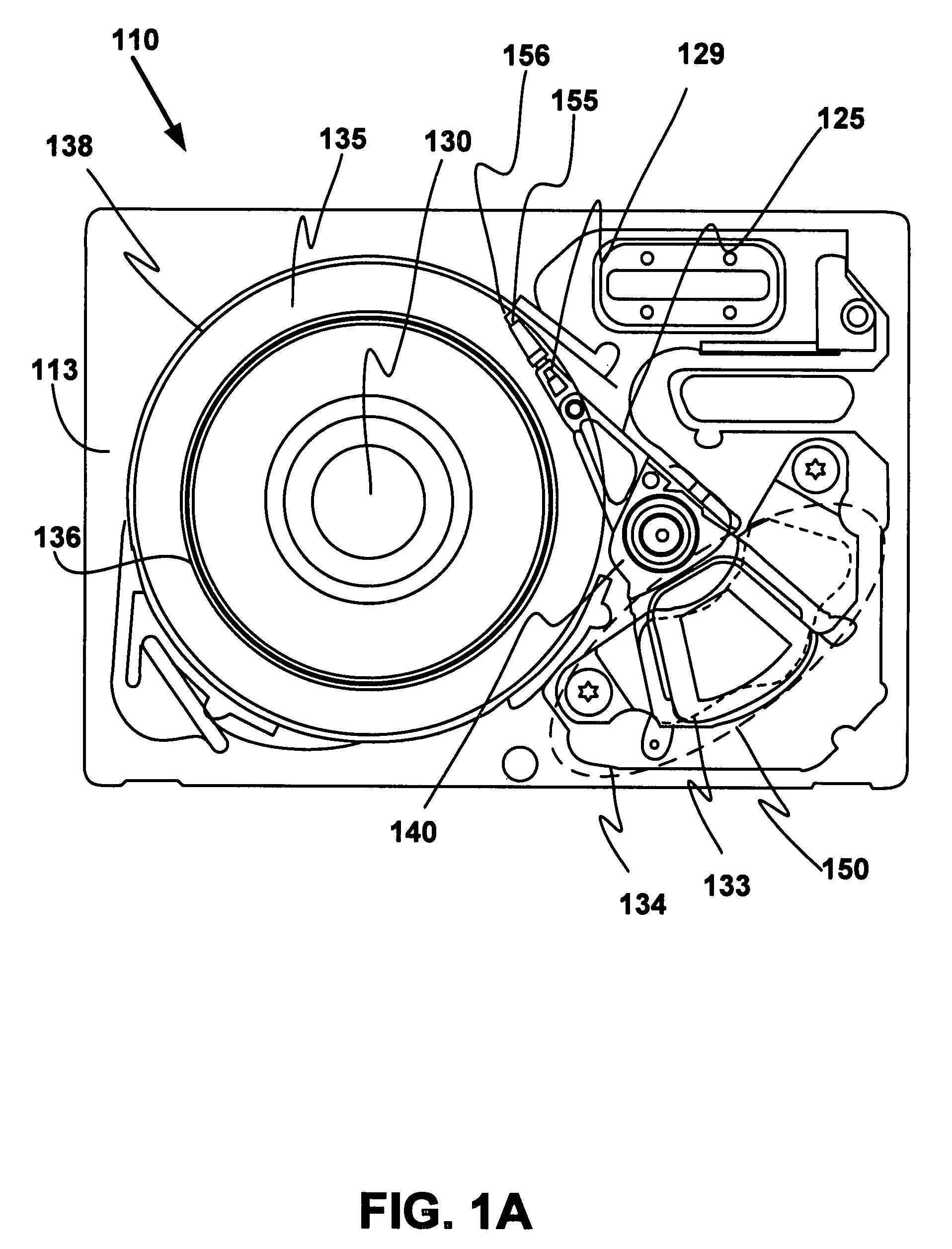
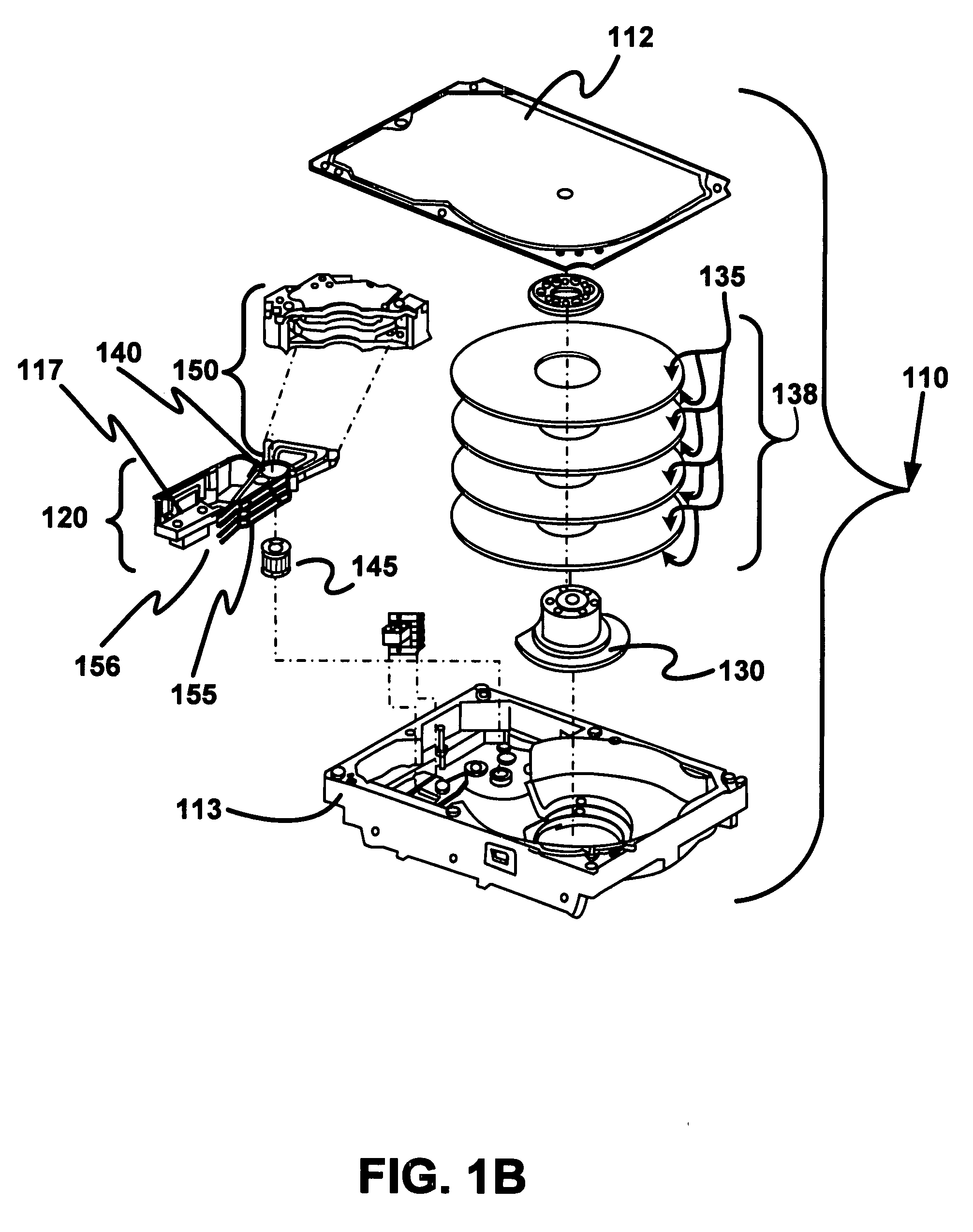
Plurality of non-magnetic dampers on a voice coil yoke arm

a non-magnetic damper and voice coil technology, applied in the field of hard disk drive development, can solve the problems of affecting deleteriously the performance of the hdd, variations in the magnetic spacing between the head element and the media, and most computing systems are not operational, so as to reduce the frequency of vibration

Inactive Publication Date: 2008-12-18
WESTERN DIGITAL TECH INC
View PDF8 Cites 7 Cited by
  • Summary
  • Abstract
  • Description
  • Claims
  • Application Information

AI Technical Summary

Benefits of technology

The patent text describes a way to reduce vibration in a hard disk drive by adding non-magnetic dampers to the voice coil yoke arm. This helps to damp low-frequency vibrations caused by the voice coil and yoke arm. The result is smoother operation of the hard disk drive and better performance.

Problems solved by technology

In fact, most computing systems are not operational without some type of hard disk drive to store the most basic computing information such as the boot operation, the operating system, the applications, and the like.
Due to the tight tolerances, any vibration activity that is realized anywhere on the entire actuator arm, can deleteriously affect the performance of the HDD.
For example, vibration of the actuator can result in variations in the magnetic spacing between the head element and media.
That is, small vibrations can cause large off-track and hence degraded performances.
Due to the TPI increase, it is more and more difficult to meet the actuator vibration requirements by controlling only voice coil motor (VCM) / actuator coil centerline tolerances, while still maintaining light structure for fast-move-time performance requirement.
In many cases, the variations in the magnetic spacing between the head element and media, the off-track issues and the increase in TPI are likely to cause data errors—both hard errors during writing and soft errors during reading.
Moreover, vibration induced errors become even more apparent as the actual offset distances and overall components are reduced in size.

Method used


Image

  • Plurality of non-magnetic dampers on a voice coil yoke arm
  • Plurality of non-magnetic dampers on a voice coil yoke arm
  • Plurality of non-magnetic dampers on a voice coil yoke arm

Examples


Embodiment Construction

[0017]Reference will now be made in detail to the alternative embodiment(s) of the present invention. While the invention will be described in conjunction with the alternative embodiment(s), it will be understood that they are not intended to limit the invention to these embodiments. On the contrary, the invention is intended to cover alternatives, modifications and equivalents, which may be included within the spirit and scope of the invention as defined by the appended claims.

[0018]Furthermore, in the following detailed description of the present invention, numerous specific details are set forth in order to provide a thorough understanding of the present invention. However, it will be recognized by one of ordinary skill in the art that the present invention may be practiced without these specific details. In other instances, well known methods, procedures, components, and circuits have not been described in detail as not to unnecessarily obscure aspects of the present invention.

[...


PUM

PropertyMeasurementUnit
diameteraaaaaaaaaa
diametersaaaaaaaaaa
frequencyaaaaaaaaaa

Abstract

A plurality of non-magnetic dampers on a voice coil yoke arm for reducing low frequency vibration in a hard disk drive is disclosed. One embodiment provides housing and at least one disk coupled with the housing. In addition, an actuator is coupled to the housing, the actuator having a coil region with a voice coil and a plurality of voice coil yoke arms. At least one of a plurality of non-magnetic dampers is also coupled with each of the plurality of voice coil yoke arms and not with the voice coil. In so doing, the plurality of non-magnetic dampers are able to damp low frequency actuator coil torsion and coil bending resonances.

Description

TECHNICAL FIELD[0001]The present invention relates to the field of hard disk drive development, and more particularly to a method and system for utilizing a plurality of non-magnetic dampers on a voice coil yoke arm to reduce low frequency vibration in a hard disk drive.BACKGROUND ART[0002]Hard disk drives (HDD) are used in almost all computer system operations. In fact, most computing systems are not operational without some type of hard disk drive to store the most basic computing information such as the boot operation, the operating system, the applications, and the like. In general, the hard disk drive is a device which may or may not be removable, but without which the computing system will generally not operate.[0003]The basic hard disk drive model includes a storage disk or hard disk that spins at a designed rotational speed. An actuator arm with a suspended slider is utilized to reach out over the disk. The slider is coupled with a suspension that supports both the body of t...

Claims


Application Information

Patent Timeline
Patent Type & Authority Applications(United States)
IPC IPC(8): G11B33/08
CPCG11B25/043G11B33/08
Inventor FU, TA-CHANGKERNER, JEFFREY
Owner WESTERN DIGITAL TECH INC
Learn More