
Turbocharger bearing with improved durability and noise reduction

a technology of bearings and turbochargers, applied in the field of bearings with improved durability and noise reduction, to achieve the effect of reducing the vibration of the sha

Active Publication Date: 2019-04-16
GM GLOBAL TECH OPERATIONS LLC
View PDF6 Cites 2 Cited by
  • Summary
  • Abstract
  • Description
  • Claims
  • Application Information

AI Technical Summary

Benefits of technology

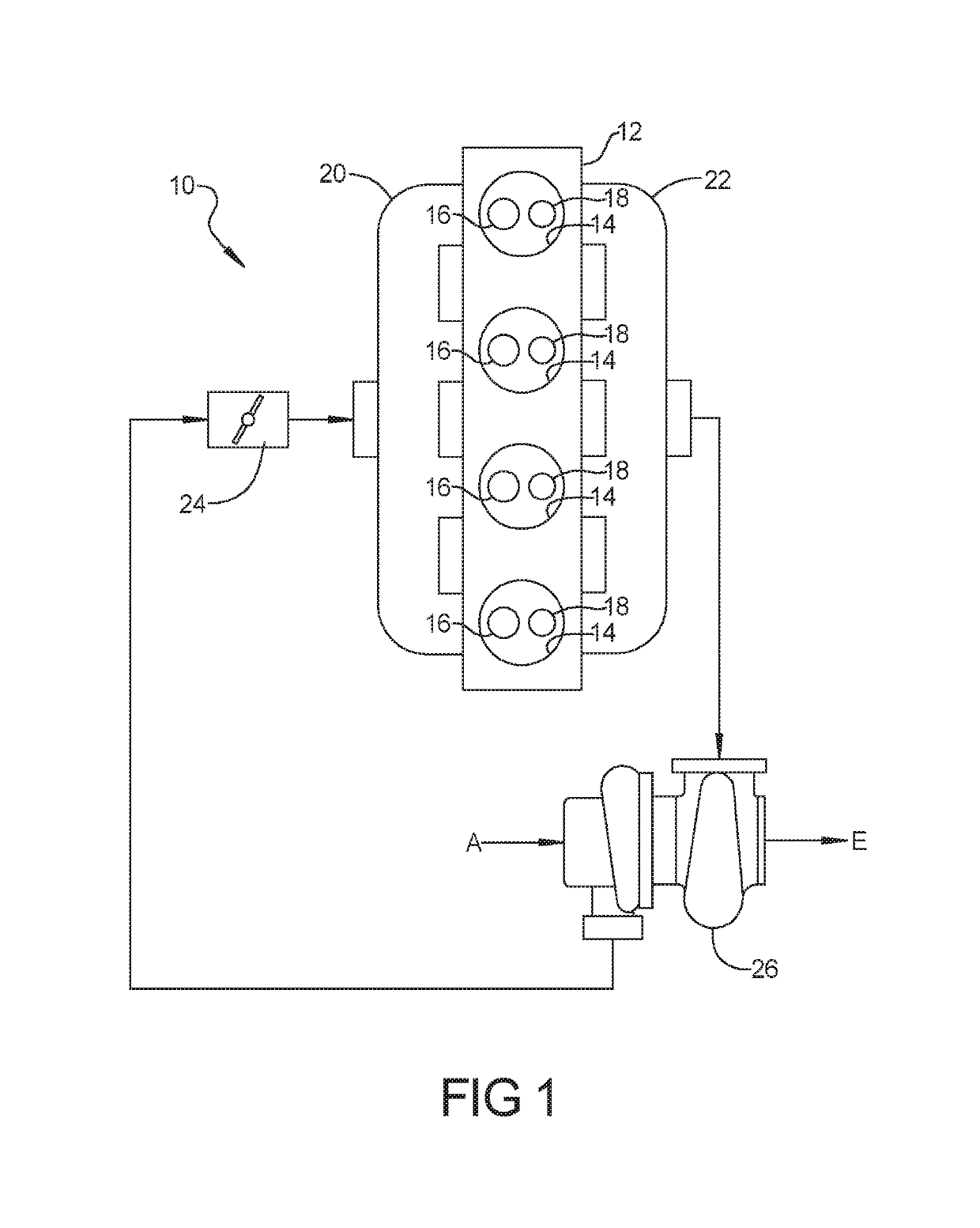
[0003]Internal combustion engines are used to generate considerable levels of power for prolonged periods of time on a dependable basis. Many such engine assemblies employ a boosting device, such as an exhaust gas turbine driven turbocharger, to compress the airflow before it enters the intake manifold of the engine in order to increase power and efficiency.
[0004]Specifically, a turbocharger utilizes a centrifugal gas compressor that forces more air and, thus, more oxygen into the combustion chambers of the engine than is otherwise achievable with ambient atmospheric pressure. The additional mass of oxygen-containing air that is forced into the engine improves the engine's volumetric efficiency, allowing it to burn more fuel in a given cycle, and thereby produce more power.
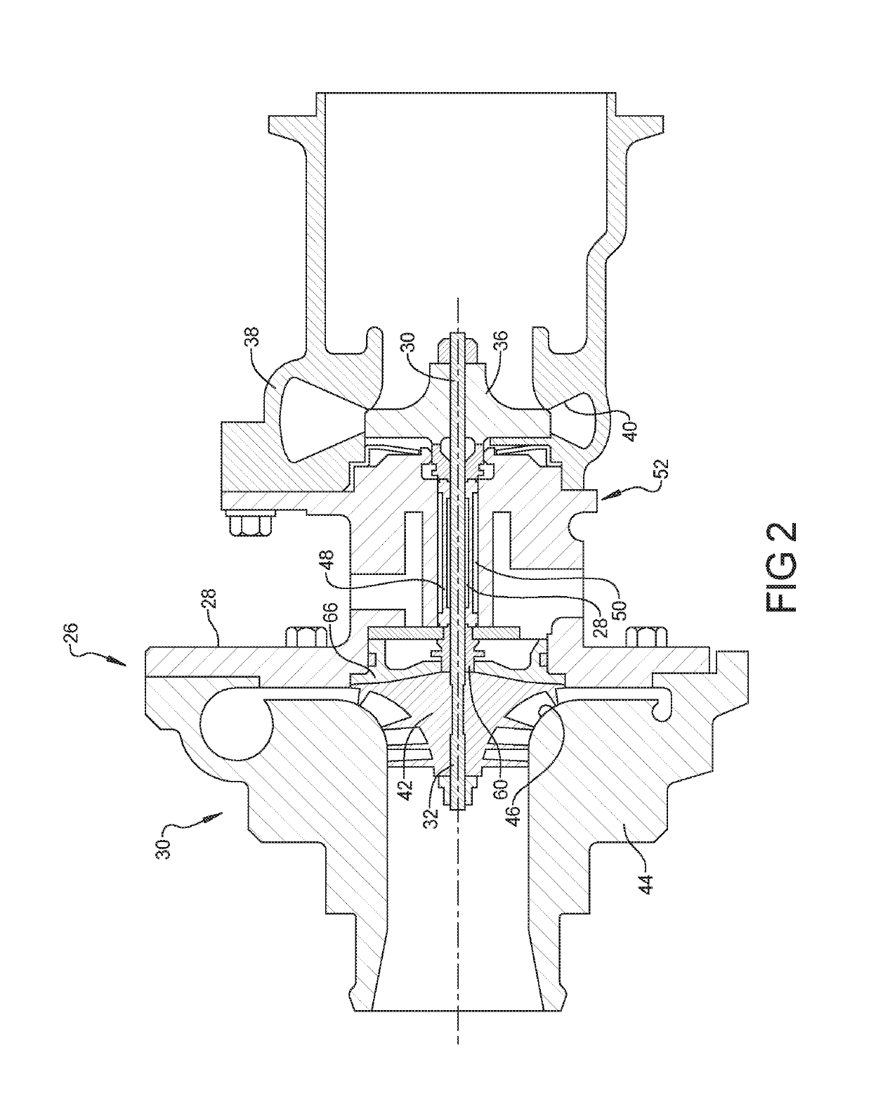
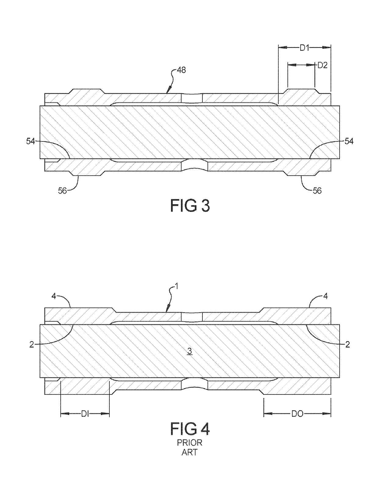
[0007]However, it is a discovery of the present application that a reduced outer bearing surface axial dimension relative to the inner bearing surface axial dimension can decrease sub-synchronous frequency vibrations. Accordingly, the present disclosure provides a turbocharger including a housing and a rotary assembly disposed within the housing and including a turbine wheel and a compressor wheel attached to one another by a shaft. A bearing is disposed in the housing and rotatably supports the shaft. The bearing includes a pair of inner bearing surfaces that engage opposite ends of the shaft and a pair of outer bearing surfaces that engage the housing. The pair of inner bearing surfaces have a first axial dimension and the pair of outer bearing surfaces have a second axial dimension that is smaller than the first axial dimension.
[0026]The effect of the relative reduced axial dimension D2 of the outer bearing surfaces 56 of the bearing 48 can be modeled by a mass-spring-damper system as illustrated in FIG. 5. In the diagram of FIG. 5, the bearing 48 is shown with a spring and damper system representing an oil film 58 between the bearing 48 and the housing 52 and with a spring and damper system representing the oil film 60 between the bearing 48 and the shaft 28. The spring and damper systems 58, 60 are represented by spring constants k1, k2 and damping coefficients c1, c2. When the turbocharger 26 does a speed ramp-up, the self-induced oil whirl in the inner film 60 will excite the rotor-dynamic natural frequency (called sub-2 conical model), the magnitude of the vibration X2 and force F1 depends on the interaction between the spring constants and damping coefficients k1, c1 and k2, c2 which are governed by the bearing design. The reduced axial dimension of the outer film 58 reduces the k1, c1 and numerically proves to be able to significantly reduce the vibration of the shaft and the interaction force between the bearing 48 and the shaft 28.

Problems solved by technology

Sub synchronous frequency vibration noise can be a concern in a turbocharger.

Method used


Image

  • Turbocharger bearing with improved durability and noise reduction
  • Turbocharger bearing with improved durability and noise reduction
  • Turbocharger bearing with improved durability and noise reduction

Examples


Embodiment Construction

[0016]Example embodiments will now be described more fully with reference to the accompanying drawings.

[0017]Example embodiments are provided so that this disclosure will be thorough, and will fully convey the scope to those who are skilled in the art. Numerous specific details are set forth such as examples of specific components, devices, and methods, to provide a thorough understanding of embodiments of the present disclosure. It will be apparent to those skilled in the art that specific details need not be employed, that example embodiments may be embodied in many different forms and that neither should be construed to limit the scope of the disclosure. In some example embodiments, well-known processes, well-known device structures, and well-known technologies are not described in detail.

[0018]The terminology used herein is for the purpose of describing particular example embodiments only and is not intended to be limiting. As used herein, the singular forms “a,”“an,” and “the” ...


PUM


Abstract

A turbocharger includes a housing and a rotary assembly disposed within the housing and including a turbine wheel and a compressor wheel attached to one another by a shaft. A bearing is disposed in the housing and rotatably supports the shaft. The bearing includes a pair of inner bearing surfaces that engage opposite ends of the shaft and a pair of outer bearing surfaces that engage the housing. The pair of inner bearing surfaces have a first axial dimension and the pair of outer bearing surfaces have a second axial dimension that is smaller than the first axial dimension.

Description

FIELD[0001]The present disclosure relates to turbochargers and more particularly to a bearing system with improved durability and noise reduction.BACKGROUND AND SUMMARY[0002]This section provides background information related to the present disclosure which is not necessarily prior art.[0003]Internal combustion engines are used to generate considerable levels of power for prolonged periods of time on a dependable basis. Many such engine assemblies employ a boosting device, such as an exhaust gas turbine driven turbocharger, to compress the airflow before it enters the intake manifold of the engine in order to increase power and efficiency.[0004]Specifically, a turbocharger utilizes a centrifugal gas compressor that forces more air and, thus, more oxygen into the combustion chambers of the engine than is otherwise achievable with ambient atmospheric pressure. The additional mass of oxygen-containing air that is forced into the engine improves the engine's volumetric efficiency, allo...

Claims


Application Information

Patent Timeline
Patent Type & Authority Patents(United States)
IPC IPC(8): F01D25/16F04D29/057F16C17/24F16C17/26F04D29/42F04D29/66F16C25/00F04D29/056F02M26/04F04D17/10
CPCF04D29/056F01D25/16F02M26/04F04D17/10F04D29/057F04D29/4206F16C17/24F16C17/26F16C25/00F04D29/663F16C2360/24F04D29/668F05D2220/40F05D2240/50F01D25/04F16C32/06F16C33/04
Inventor SHI, FANGHUIDENG, DINGFENGWU, RANBEGIN, LOUIS P.
Owner GM GLOBAL TECH OPERATIONS LLC
Learn More