
Motor controller

a technology of motor controller and motor controller, which is applied in the direction of motor control for motor oscillation damping, program control, instruments, etc., can solve the problem of not revealing a method of reducing vibration in the motor controller for speed control, and achieve the effect of reducing vibration in the drive uni

Active Publication Date: 2018-12-27
FANUC LTD
View PDF0 Cites 3 Cited by
  • Summary
  • Abstract
  • Description
  • Claims
  • Application Information

AI Technical Summary

Benefits of technology

The present invention provides a motor controller that can reduce vibrations in the drive unit of a machine by performing speed control based on a speed command. This helps to improve the accuracy and stability of the control system.

Problems solved by technology

Although Patent Documents 1 and 2 disclose a method of reducing vibrations in the motor controller for performing the position control, they do not disclose a method of reducing vibrations in a motor controller for performing speed control.

Method used


Image

  • Motor controller
  • Motor controller
  • Motor controller

Examples


Embodiment Construction

[0020]An example of an embodiment of the present invention will be described below with reference to accompanying drawings. In the drawings, the same or corresponding portions are identified with the same reference numerals.

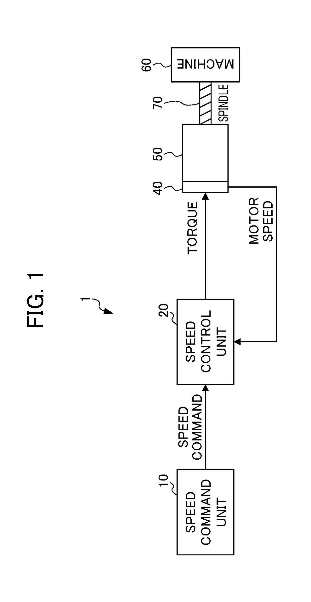
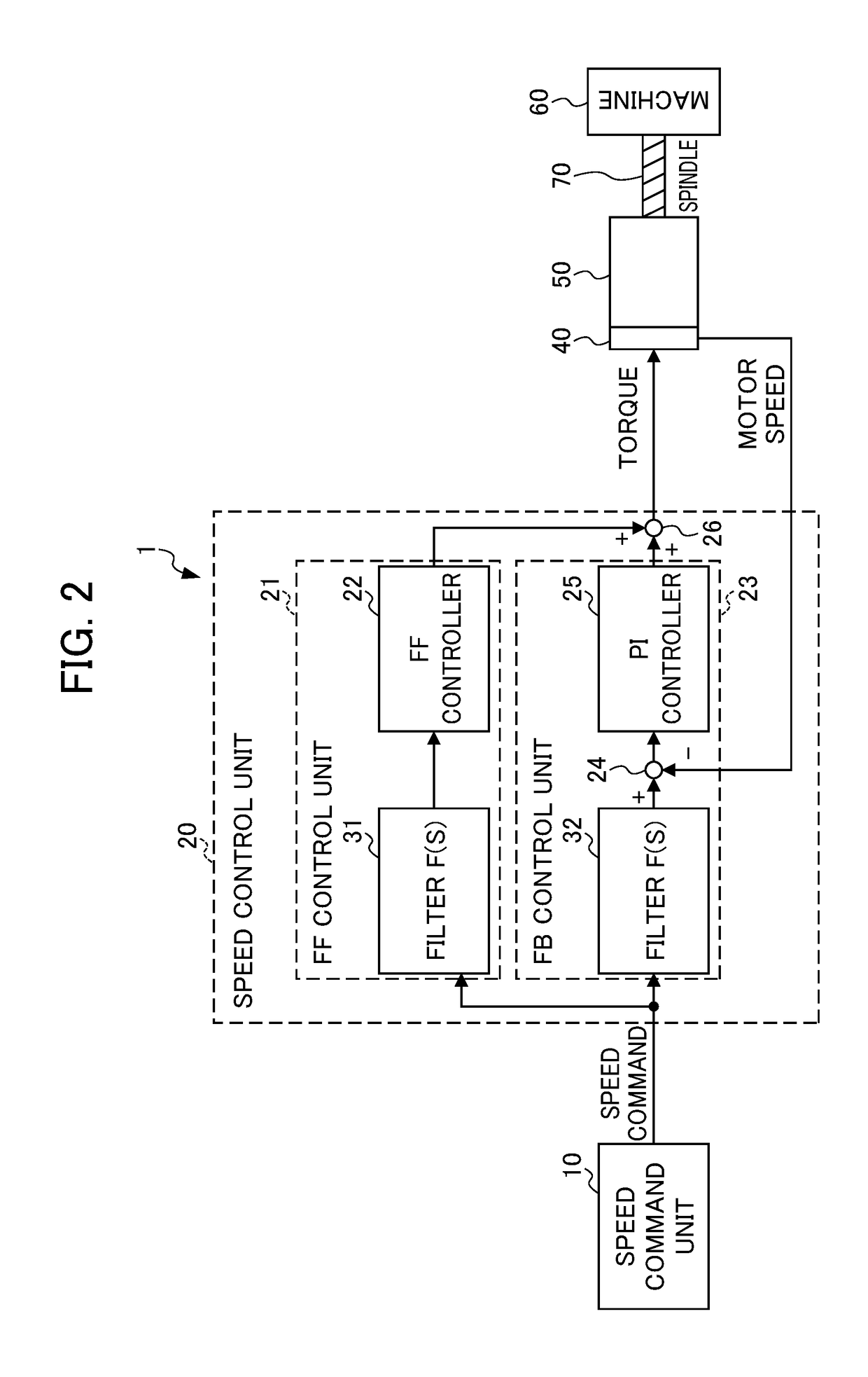
[0021]FIG. 1 is a schematic view of the configuration of a motor controller according to the present embodiment, and FIG. 2 is a diagram showing in detail the configuration of the motor controller according to the present embodiment. The motor controller 1 shown in FIGS. 1 and 2 controls the speed of a servo motor 50 based on a speed command value corresponding to a machining program and an actual motor speed value (speed feedback value). The servo motor 50 is coupled to a ball screw 70 in a machine 60. The servo motor 50 rotates and drives the ball screw (drive unit) 70 so as to drive the machine 60. The motor controller 1 includes a speed command unit 10, a speed control unit 20 and an encoder (speed detection unit) 40.

[0022]The speed command unit 10 produces t...


PUM


Abstract

A motor controller which controls a servo motor for driving a machine, includes: a speed command unit which commands the speed of the machine; a speed detection unit which detects the speed of the servo motor; and a speed control unit which produces a torque command based on a speed command and a motor speed detected so as to control the speed of the servo motor, where the speed control unit includes a filter which approximates the inverse characteristic of a transmission characteristic from the servo motor to the machine, the filter has a transmission characteristic F(s) based on a frequency ω, a vibration damping coefficient ζ and a cutoff frequency ωadj which are adjustment parameters and the frequency ω is adjusted so as to be equal to or more than an antiresonant frequency ω0 of the machine but less than a resonant frequency ωp.

Description

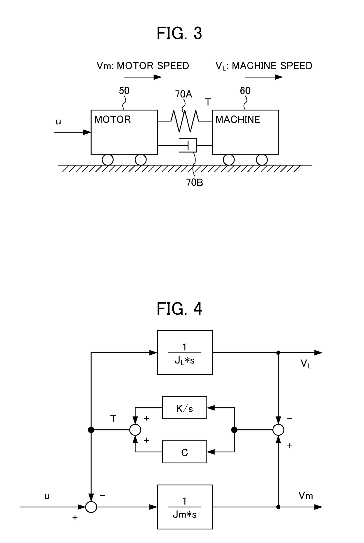
[0001]This application is based on and claims the benefit of priority from Japanese Patent application No. 2017-121341, filed on Jun. 21, 2017, the content of which is incorporated herein by reference.BACKGROUND OF THE INVENTIONField of the Invention[0002]The present invention relates to a motor controller which controls a servo motor.Related Art[0003]For example, in a machine tool, a motor controller known which controls a servo motor so as to drive a feed axis. When in the machine tool described above, the servo motor and a machine are coupled with the feed axis such as a ball screw, the rigidity of the feed axis is low such that e servo motor and the machine are brought into a state of spring coupling. Due to the spring coupling, in the feed axis of the machine, low-frequency resonance (vibration) in a servo control band may occur.[0004]As a method of reducing the low-frequency resonance (vibration) described above, a method of correcting a position command, a method of using a f...

Claims


Application Information

Patent Timeline
IPC IPC(8): G05B19/23
CPCG05B19/237G05B2219/41118G05B2219/41166G05B2219/41437G05B2219/41426G05B2219/42065H02P23/0004H02P23/04
Inventor NAKAMURA, TSUTOMUIKAI, SATOSHI
Owner FANUC LTD
Learn More