Stuctural Beam for a Wind Generator Blade Production Method Thereof

a technology of structural beams and wind turbine blades, applied in the manufacture of final products, machines/engines, other domestic articles, etc., can solve the problems of wind turbine blades with structural components specifically designed to be the subject of an efficient mechanised manufacturing process, and the knowledge of the problem is not known

Active Publication Date: 2008-12-18
GAMESA INNOVATION & TECH SA
View PDF5 Cites 34 Cited by
  • Summary
  • Abstract
  • Description
  • Claims
  • Application Information

AI Technical Summary

Problems solved by technology

However, wind turbine blades with a structural component specifically designed to be the subject of an efficient mechanised manufacturing process are not known.

Method used


Image

  • Stuctural Beam for a Wind Generator Blade Production Method Thereof
  • Stuctural Beam for a Wind Generator Blade Production Method Thereof
  • Stuctural Beam for a Wind Generator Blade Production Method Thereof

Examples


Embodiment Construction

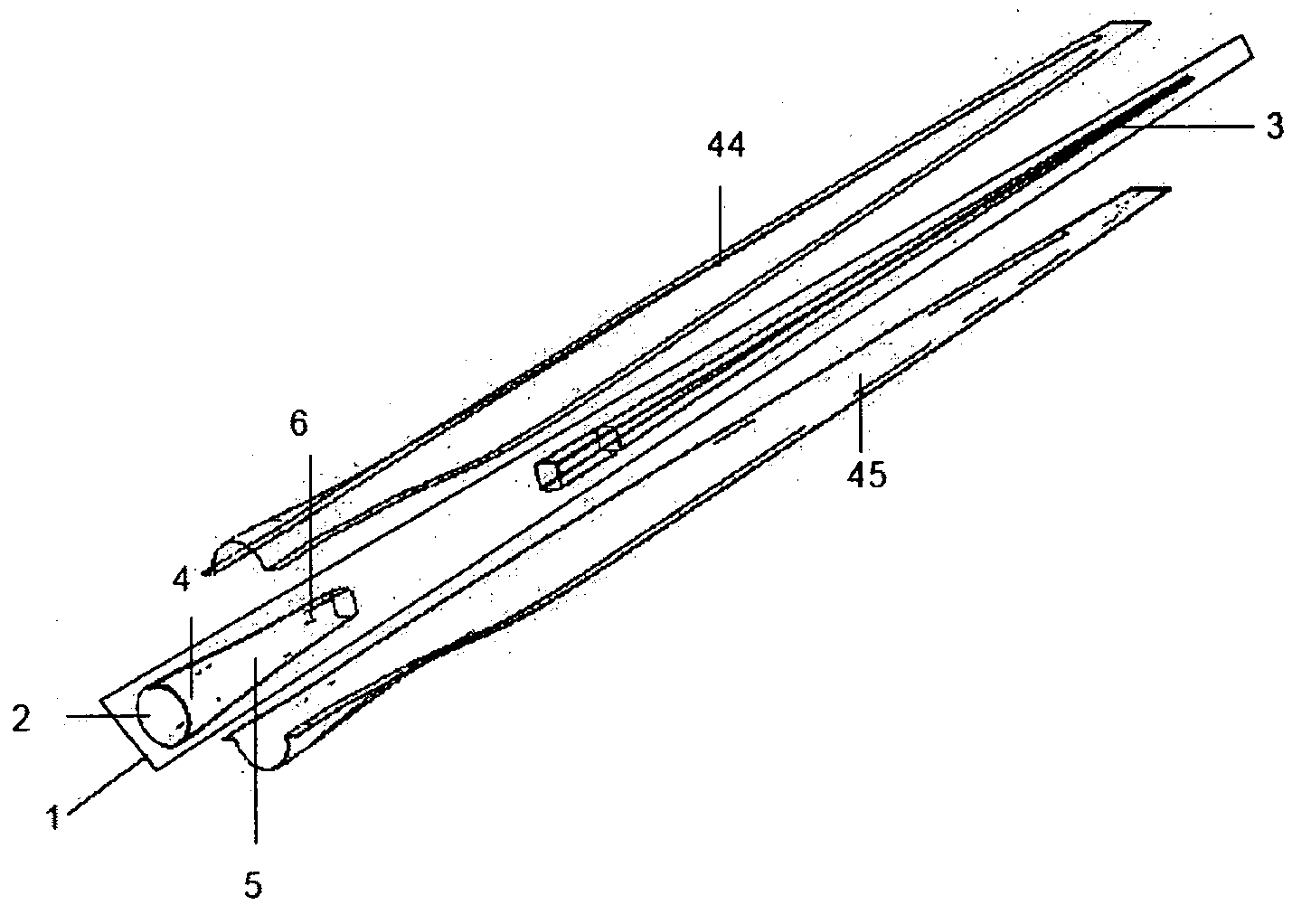
[0009]Firstly, this invention proposes a specific design of the structural beam of a wind turbine blade, and secondly, a manufacturing procedure for said blade which is susceptible to mechanisation with a high degree of automation.

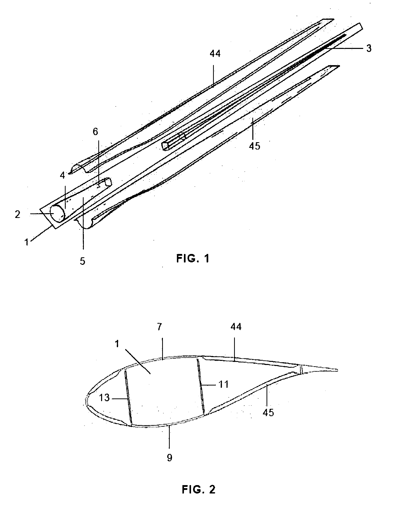
[0010]The structural beam proposed is formed, as is the known technique, by a first body or root body with a first cylindrical shaped part close to the wind turbine hub, a third box shaped part and a second part with a transitional shape, and a second body, which further will be referred to as body-trunk.

[0011]According to this invention, in its first point, this body-trunk which is shaped in the form of a box with a decreasing section towards the blade tip comprises various piles, each formed by various layers of carbon fibre impregnated with a synthetic resin, located on the upper and lower areas, intercalated between various layers of fibre glass impregnated with synthetic resin arranged along its perimeter, also including a layer of reinforcing materia...


PUM

PropertyMeasurementUnit
pressureaaaaaaaaaa
pressureaaaaaaaaaa
shapeaaaaaaaaaa

Abstract

Structural beam of a wind turbine blade comprising a body-root and a body-trunk in the form of a box with a section decreasing towards the blade tip, comprising various piles each formed by various layers of carbon fibre impregnated with a synthetic resin, located on the upper and lower areas, intercalated between various layers of fibre glass impregnated with synthetic resin arranged along its perimeter, including between two piles, at least one layer of reinforcing material on each of the side areas enveloped by an adhesive resin film.The invention also comprises a procedure for the manufacture of the structural beam which, amongst other stages, includes the application of the layers mentioned onto a mould and the beam curing process.

Description

FIELD OF THE INVENTION[0001]This invention relates to a structural beam manufactured in composite material, based on fibre glass, carbon fibre and synthetic resin and in particular to the structural beam of a wind turbine blade and the manufacturing process of said beam.BACKGROUND OF THE INVENTION[0002]The structural components of wind turbine blades must be designed to support the stresses caused by their continuous working conditions, and to weigh as little as possible. This is why composite materials have been used for their manufacture.[0003]However, wind turbine blades with a structural component specifically designed to be the subject of an efficient mechanised manufacturing process are not known. In this regard, antecedents in the aeronautics sector are known, such as those mentioned below.[0004]Document PCT WO 84 / 04905 describes a manufacturing process for covering an aeroplane wing in a composite material, in which the demoulding is carried out by applying pneumatic pressur...

Claims


Application Information

Patent Timeline
Patent Type & Authority Applications(United States)
IPC IPC(8): F01D5/14B29D99/00
CPCB29C70/44B29L2031/08B29L2031/085F03D1/0675Y02E10/721B29C53/58B29C70/32Y02E10/72Y02P70/50F03D1/065
Inventor LLORENTE GONZALEZ, JOSE IGNACIOVELEZ ORIA, SERGIO
Owner GAMESA INNOVATION & TECH SA
Why Eureka
Try Eureka