
Lauter tun false bottom

a false bottom and lauter tun technology, applied in the field of beer brewing industry, can solve the problems of easy plugging and uneven filtration distribution

Active Publication Date: 2008-12-18
BLICHMANN JOHN RICHARD
View PDF5 Cites 10 Cited by
  • Summary
  • Abstract
  • Description
  • Claims
  • Application Information

AI Technical Summary

Problems solved by technology

While this method has a nearly 100% even distribution of filtration, it tends to plug easily.
While this device does not plug easily, the filtration distribution is uneven due to the spacing of the manifold pipes and wort is wasted.

Method used


Image

  • Lauter tun false bottom
  • Lauter tun false bottom
  • Lauter tun false bottom

Examples


Embodiment Construction

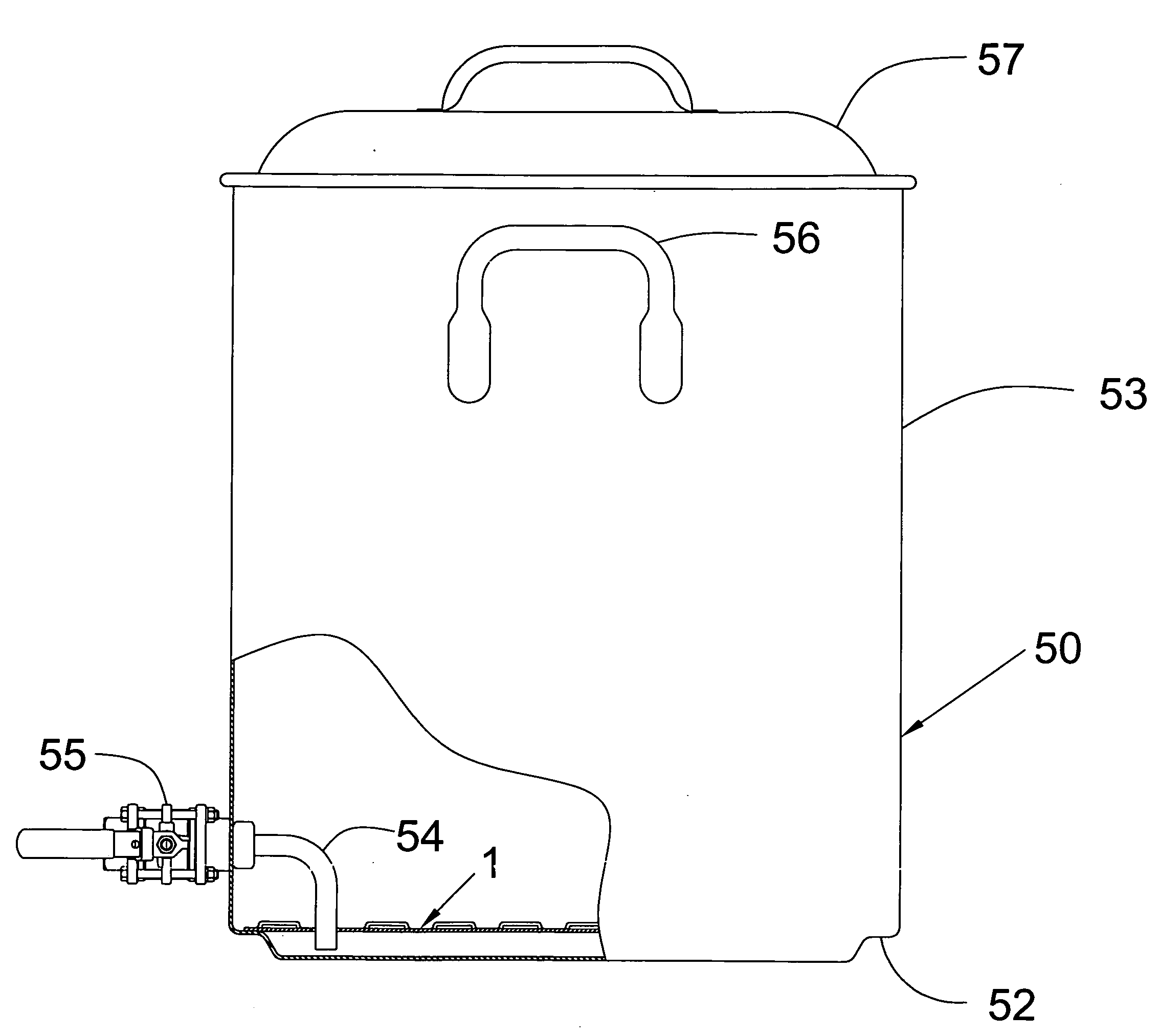
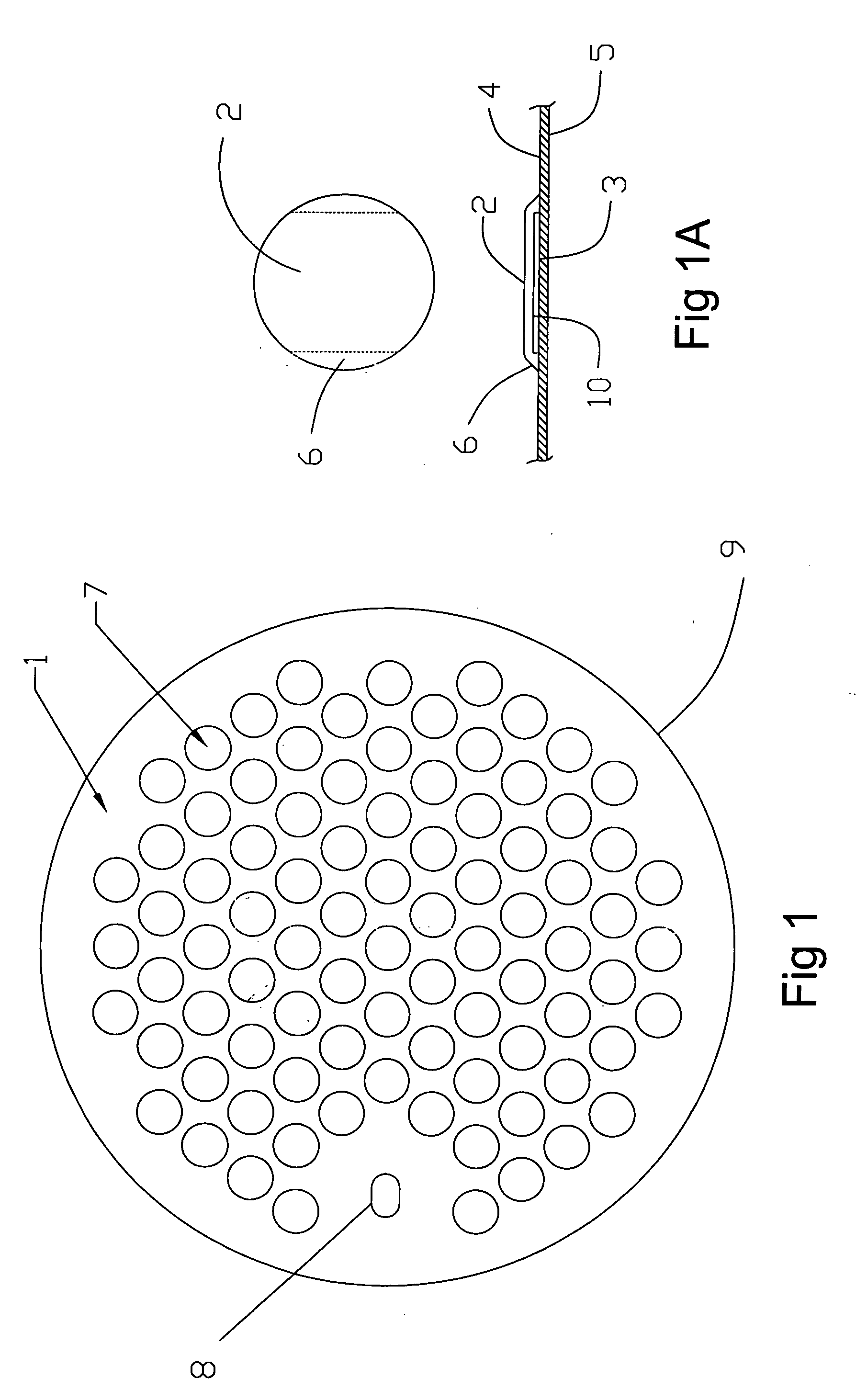
[0002]Referring to FIG. 1, a louvered false bottom 1 of a lauter tun is shown. This bottom has a plurality of raised louvers 7 more or less evenly spaced over the false bottom. Louvered false bottom has a top surface 4, a bottom surface 5, and an outer edge 9. In addition, louvered false bottom 1 has a drain tube hole 8. As shown in FIG. 1 and FIG. 1A, a raised louver 7 has a top surface 2, a bottom surface 3, a leg 6, and a slot 10.

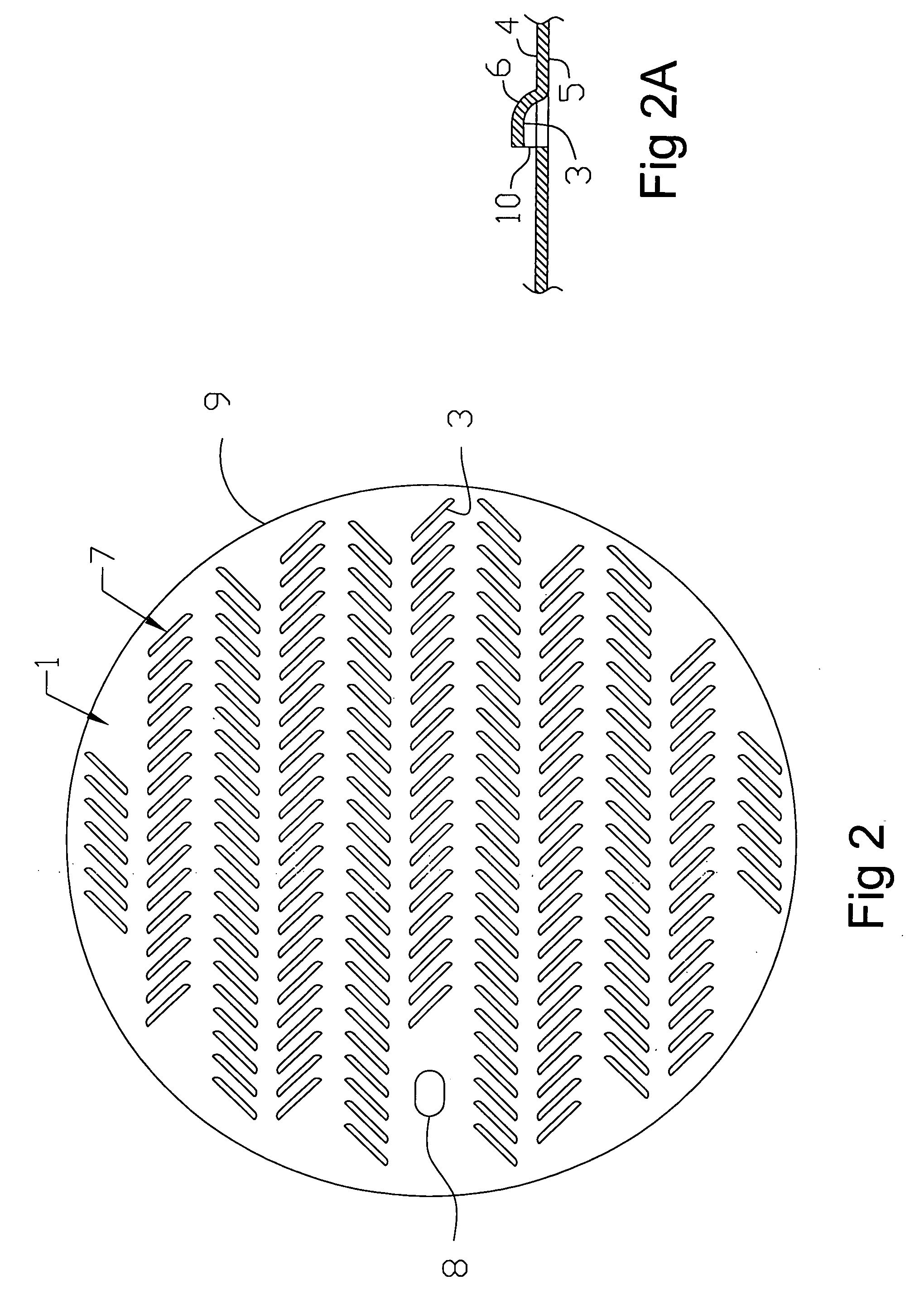
[0003]FIG. 2 and FIG. 2A show an embodiment of the invention, herein the plurality of louvers 7 are shaped in an elongated fashion.

[0004]FIG. 3 shows a prior art slotted manifold assembly 20 made from elbows 22, tee's 23, slotted tube 25 and outlet cross 21. Tube 25, as best shown in FIG. 3A, has an inside surface 27 and an outside surface 26. A plurality of slots 3 are placed on tube 25, usually evenly spaced extending approximately half way through tube 25.

[0005]FIG. 4 shows a prior art perforated false bottom 40 also having a top surface 4, a bottom s...


PUM

PropertyMeasurementUnit
Sizeaaaaaaaaaa

Abstract

A system for filtering spent grains from unfermented beer is disclosed. The system has a pot assembly having a stock pot wall, lid, drain tube and outlet valve. A louvered false bottom is positioned in the pot assembly and forms an opening between the false bottom and the stock pot wall. The louvered false bottom has a plurality of raised louvers spaced over the false bottom. Each of the louvers has a top surface, a bottom surface, a leg and a slot. The slot can be made larger or smaller according to the grain crush size.

Description

DISCUSSION OF PRIOR ART[0001]It is well known in the beer brewing industry to utilize a filtration system at the bottom of a lauter tun to filter the spent grains from the unfermented beer (wort) so that it can be transferred to the brew pot for further processing. Two methods are currently used. Method one is a perforated false bottom having openings extending through the false bottom. While this method has a nearly 100% even distribution of filtration, it tends to plug easily. Method two is a slotted manifold typically made from an assembly of copper pipe fittings where numerous slots have been sawed half way through and evenly spaced along the pipes. While this device does not plug easily, the filtration distribution is uneven due to the spacing of the manifold pipes and wort is wasted. The present invention overcomes both the tendency to plug, and the uneven filtration distribution, yielding a false bottom that is resistant to plugging and also exhibits even flow characteristics...

Claims


Application Information

Patent Timeline
IPC IPC(8): C12C7/17B01D43/00B01D21/02
CPCB01D43/00C12C7/17C12C13/10
Inventor BLICHMANN, JOHN RICHARD
Owner BLICHMANN JOHN RICHARD
Learn More