
Pulsed electric field apparatus and methods for ethanol production

a technology of electric field and ethanol, which is applied in the direction of biofuels, specific use bioreactors/fermenters, after-treatment of biomass, etc., can solve the problems of inefficiency of ethanol production facilities, inability of enzymes to effectively access the starch contained in microcrystalline structures, and challenge degradation

Inactive Publication Date: 2008-12-18
OPTISWITCH TECH CORP
View PDF4 Cites 18 Cited by
  • Summary
  • Abstract
  • Description
  • Claims
  • Application Information

AI Technical Summary

Benefits of technology

The apparatus and methods described here can solve problems and improve existing technologies. They offer new features and benefits for people working in this field.

Problems solved by technology

The technical problem addressed in this patent is the inefficiencies in the production of ethanol due to the presence of microcrystalline structures in starch and bacteria interfering with the conversion of sugar into ethanol. The patent aims to provide apparatus and methods that may reduce the usage of antibiotics and increase efficiency in the production of ethanol.

Method used


Image

  • Pulsed electric field apparatus and methods for ethanol production
  • Pulsed electric field apparatus and methods for ethanol production
  • Pulsed electric field apparatus and methods for ethanol production

Examples


Embodiment Construction

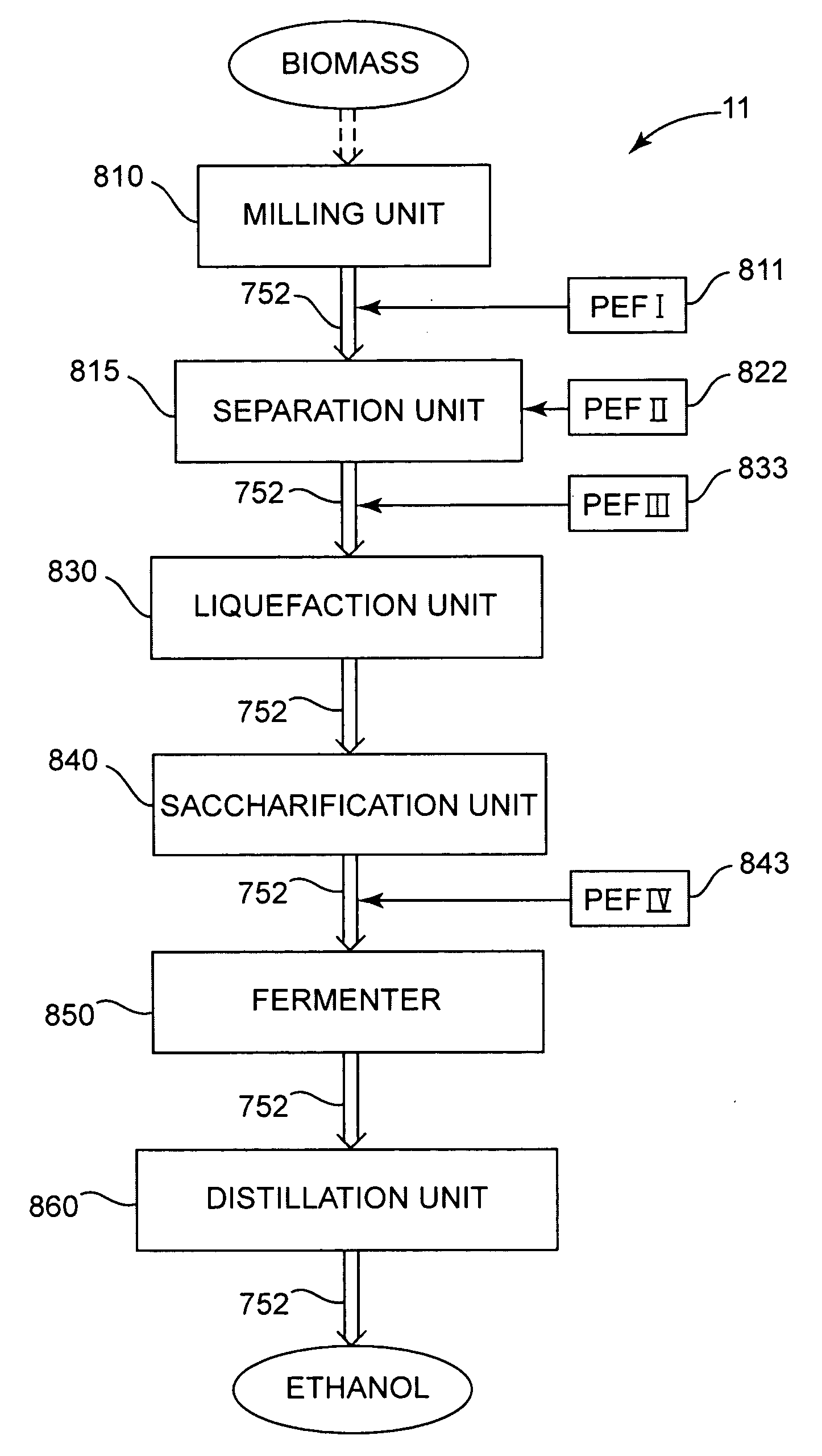
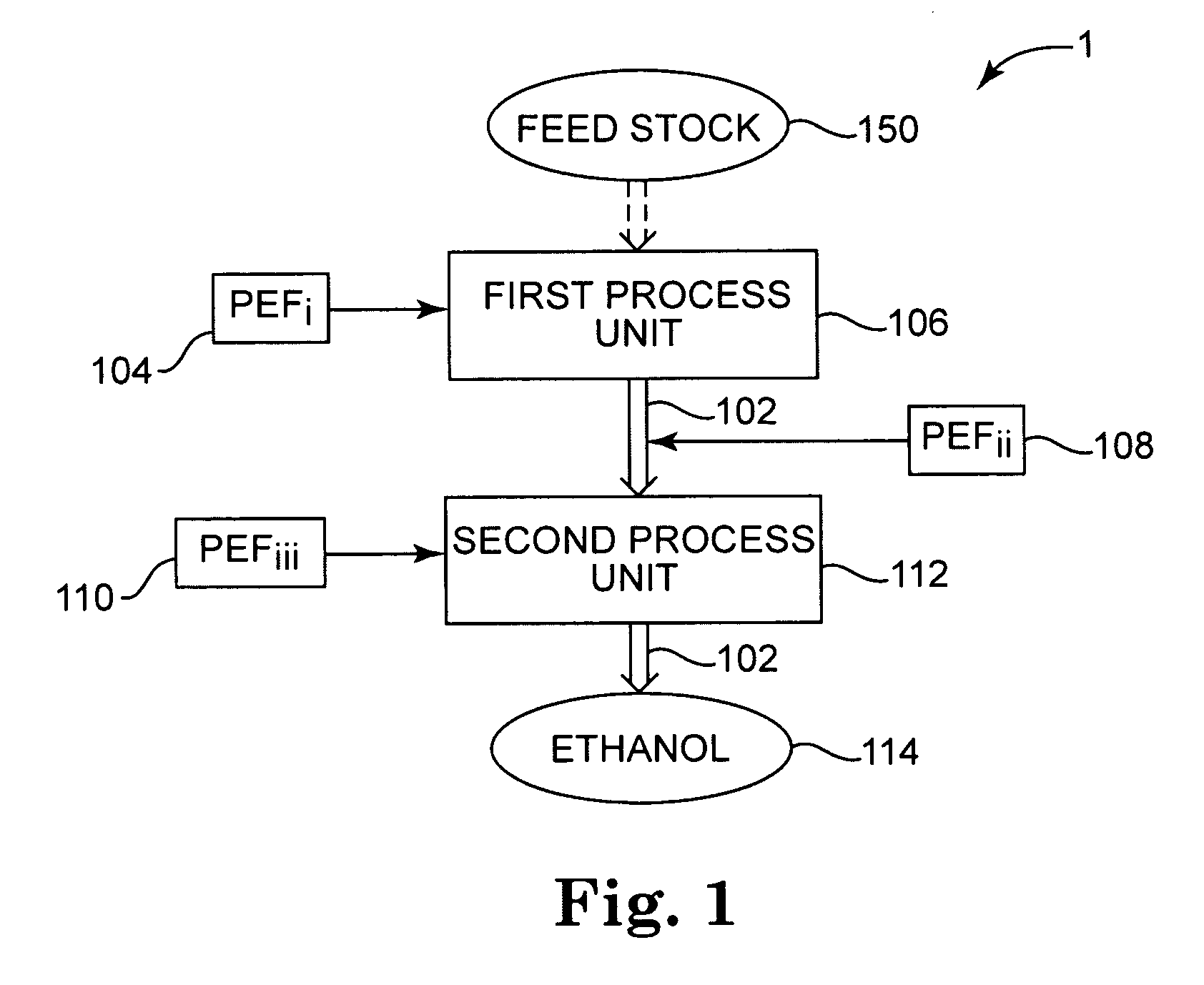
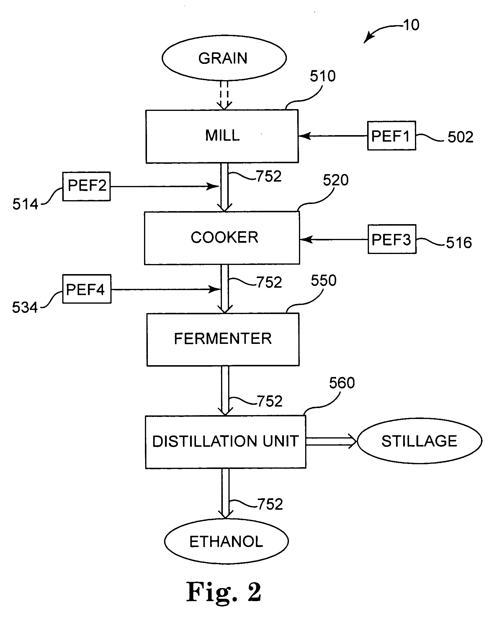
[0022]The ethanol production facility apparatus includes a plurality of process units configured to produce ethanol from a feedstock. In various aspects, the feedstock may be grain including corn, wheat, and barley or cellulosic biomass, or combinations of grain and cellulosic biomass, and the ethanol production facility apparatus may be particularly configured to produce ethanol from a grain feedstock, from a cellulosic biomass feedstock, or from combinations thereof. At least one of the process units is configured to accept the feedstock and to generate a liquid based processing stream The process units are in fluid communication to flow the liquid based processing stream amongst the process units to process the liquid based processing stream into ethanol. The ethanol production facility apparatus includes one or more pulsed electric field generators to apply a pulsed electric field (PEF) to the liquid based processing stream at a pulsed electric field location generally within th...


PUM


Abstract

Apparatus and methods for ethanol production use pulsed electric fields to increase the conversion of starch and/or cellulosic material into sugar. The pulsed electric fields may also control bacteria levels in the ethanol production facility. The pulsed electric fields may be generated by a pulsed electric field generator such as a Marx generator, which may have one or more semiconductor switches.

Description


Claims


Application Information

Patent Timeline
Owner OPTISWITCH TECH CORP
Learn More