
Intelligent air conditioning system for a paint booth

a technology for air conditioning systems and paint booths, applied in space heating and ventilation control systems, lighting and heating apparatuses, heating types, etc., can solve the problems of not considering the most economical or energy-efficient known systems, not considering the known systems for conditioning the exterior air, etc., to minimize the quality defects of paint, less energy, cost less

Inactive Publication Date: 2008-12-18
HONDA MOTOR CO LTD
View PDF59 Cites 28 Cited by
  • Summary
  • Abstract
  • Description
  • Claims
  • Application Information

AI Technical Summary

Benefits of technology

[0012]More specifically, the present invention is directed toward a conditioning system in which the exterior air is adjusted to a variable set point within a predetermined range. Variable set point selection is based upon traditional considerations for selecting a set point, such as maintaining safe conditions in the spray booth and minimizing quality defects in the paint on the vehicle. However, the variable set point selection of the present invention is also concerned with selecting a set point that uses the least amount of energy and / or that costs the least amount of money to condition the exterior air. In addition, the present invention optionally also considers selecting the variable set point based upon predicted future weather conditions. For example, less energy may be consumed or it may cost less for a variable set point to be selected on the basis of the predicted future weather conditions, rather than selecting a set point for the immediate weather conditions.

Problems solved by technology

These known systems do not account for what would be the most economical or the most energy efficient method to adjust the exterior air to the set point.
Nor do the known systems condition the exterior air based upon predicted future conditions of the exterior air.

Method used


Image

  • Intelligent air conditioning system for a paint booth
  • Intelligent air conditioning system for a paint booth
  • Intelligent air conditioning system for a paint booth

Examples


Embodiment Construction

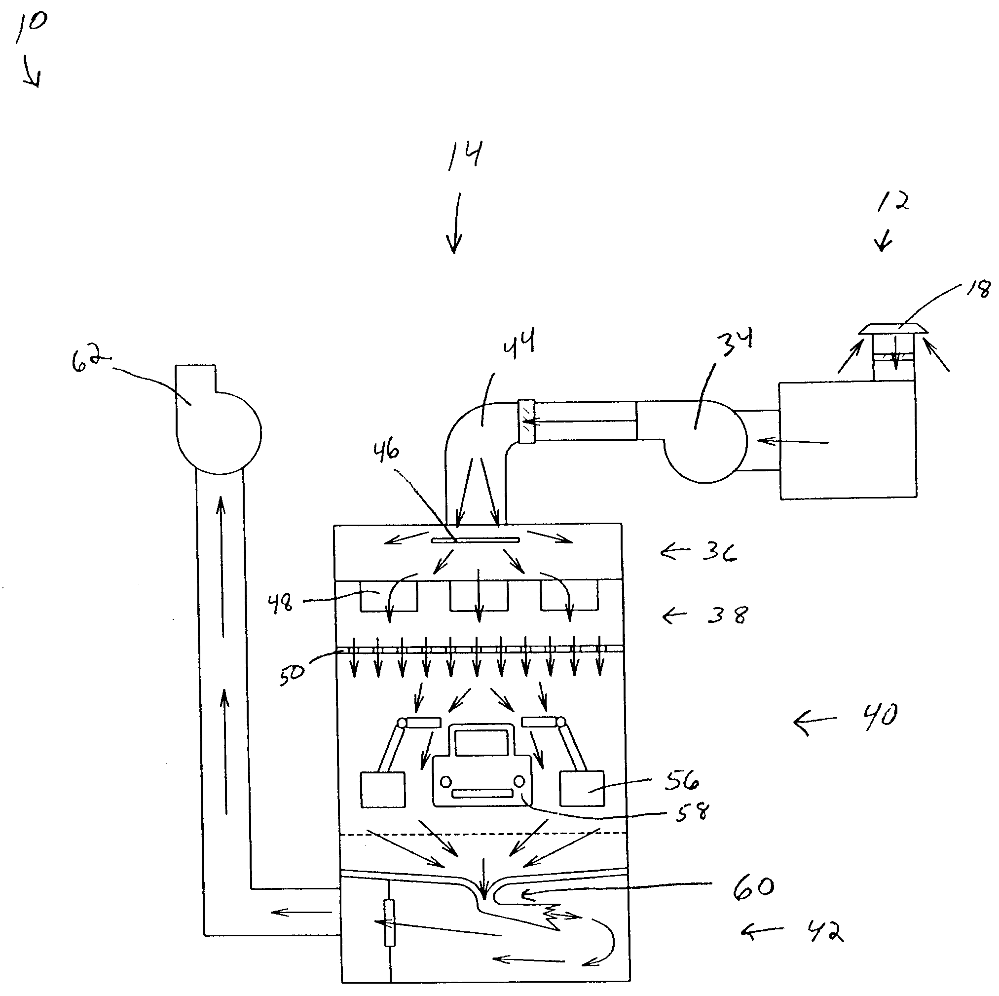
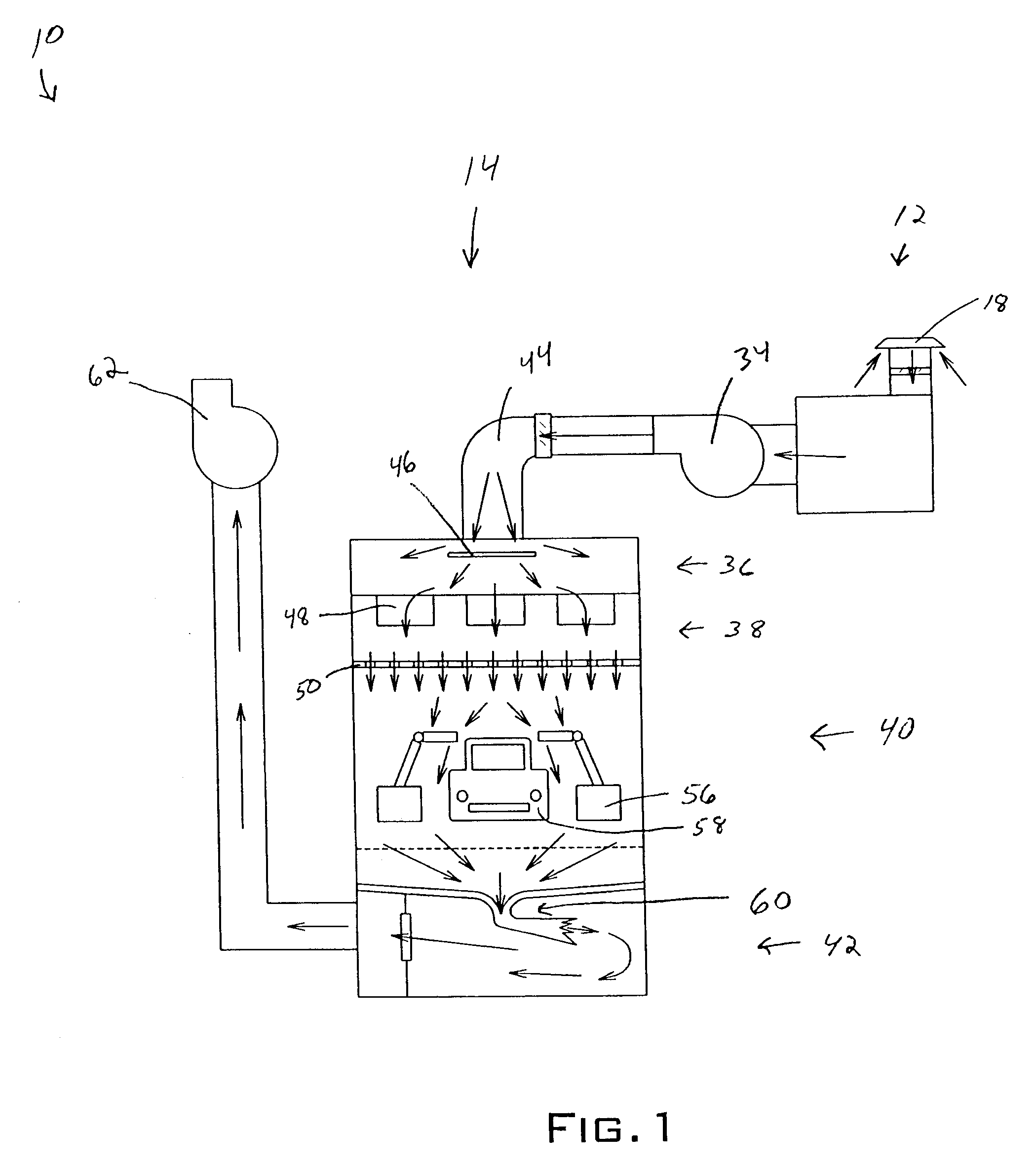
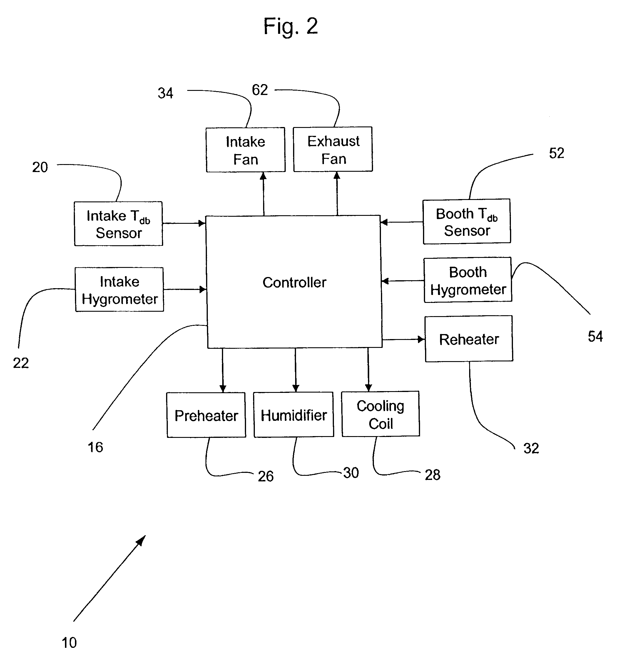
[0024]With reference to FIGS. 1-3, a conditioning system 10 for air used during the spray painting of vehicles according to the present invention is shown. A conditioning area 12 and a booth area 14 make up the conditioning system 10. The conditioning area 12 includes a controller 16, an inlet 18, an intake temperature sensor 20, an intake hygrometer 22, a first set of filters 24, a preheater 26, a cooling coil 28, a humidifier 30, a reheater 32, and an intake fan 34.

[0025]The booth area 14 is divided into an upper plenum 36, a lower plenum 38, a spray area 40, and a lower area 42. The upper plenum 36 includes an inlet tap 44 and a diffuser plate 46, while the lower plenum 38 includes a second set of filters 48 and a ceiling filter 50. The upper plenum 36 further contains a booth temperature sensor 52 and a booth hygrometer 54. The spray area 40 contains spray equipment 56 for applying paint or coatings to an object, which in this case is a vehicle 58. Below the spray area 40 are sc...


PUM


Abstract

A conditioning system that conditions exterior air for use in a spray booth. The exterior air is conditioned and subsequently used to carry away coating mist, dust, and contaminants from a spray area. The conditioning system heats, cools, humidifies, and dehumidifies the exterior air to a variable set point. The variable set point, while bounded by dry-bulb temperature and relative humidity constraints, is selected based upon cost and / or energy minimization. Additionally, the set point selection may be based upon future predicted weather conditions that are determined with a mathematical profile of previous weather conditions and weather trends in a localized domain, where the localized domain is a geographic area surrounding a manufacturing plant that includes a spray booth.

Description

BACKGROUND OF THE INVENTION[0001]1. Field of the Invention[0002]The present invention is generally directed toward paint booth air handling systems and, more particularly toward a method for conditioning exterior air for use in a paint booth.[0003]2. Description of Related Art[0004]In a spray booth for painting, for example, vehicle bodies that are continuously conveyed on a conveyor through the spray booth, the quality of the conditioned (booth ambient) air is very important. Typically, exterior (atmospheric) air is passed through a conditioning area prior to being sent into the spray booth. The conditioned air is directed by an intake fan to a plenum chamber and is discharged downwardly at a predetermined flow velocity into the spray booth. The conditioned air in the spray booth is drawn together with coating mists, including any evaporated organic solvents, and is discharged beneath the booth by an exhaust fan. This downward air flow can prevent the coating mist or dust, which wo...

Claims


Application Information

Patent Timeline
IPC IPC(8): B05B15/12F25B29/00F24F11/76
CPCB05B12/08B05B15/1222F24F11/0008F24F11/62F24F2110/20F24F11/76F24F11/30F24F2110/10F24F2130/00F24F2130/10F24F11/64B05B12/12B05B16/60F24F11/89
Inventor BHATTACHARYA, SHUBHO
Owner HONDA MOTOR CO LTD
Learn More