Apparatus and method for imaging-assisted intubation using pre-existing practitioner skill set

a technology of pre-existing skills and apparatus, applied in the field of apparatus and method for imaging-assisted intubation using pre-existing skills of practitioners, can solve the problems of inability to see around soft tissues that obstruct the needed view, lack of direct visualization of the larynx, and insufficient vocal cord visualization of the laryngoscope. to achieve the effect of facilitating indirect visualization

Inactive Publication Date: 2008-12-18
KIM TAEHOON
View PDF25 Cites 50 Cited by
  • Summary
  • Abstract
  • Description
  • Claims
  • Application Information

AI Technical Summary

Benefits of technology

[0011]What is needed is an apparatus and a method to facilitate indirect visualization during intubation that avoid problems associated with conventional intubation apparatuses, and methods, that use direct or indirect visualization.
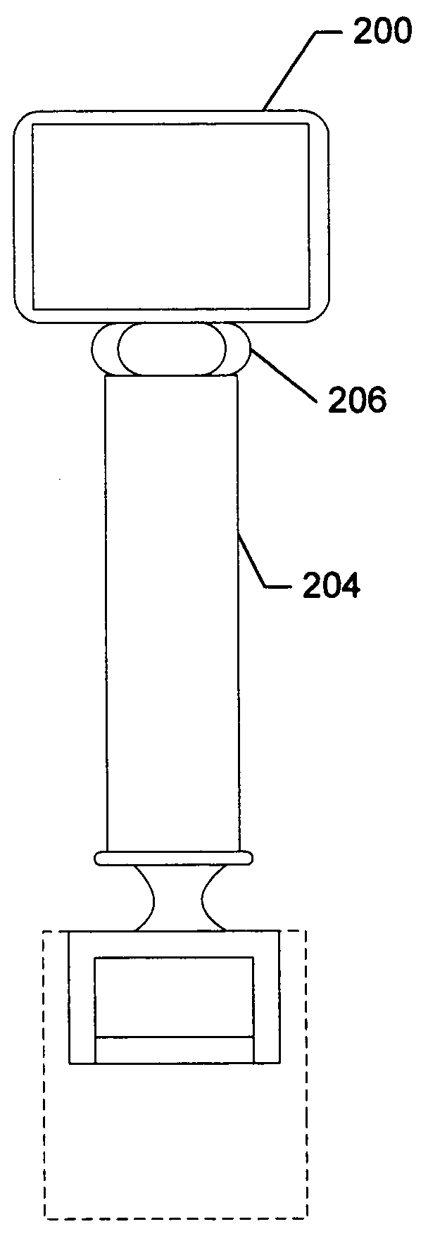
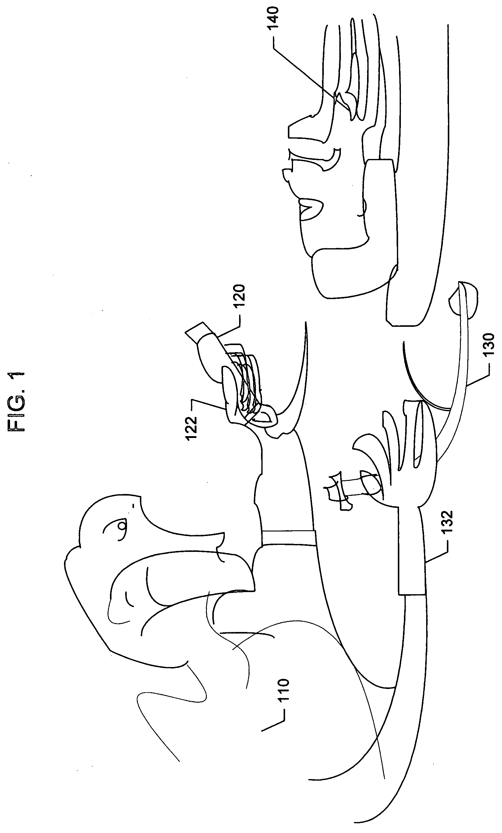
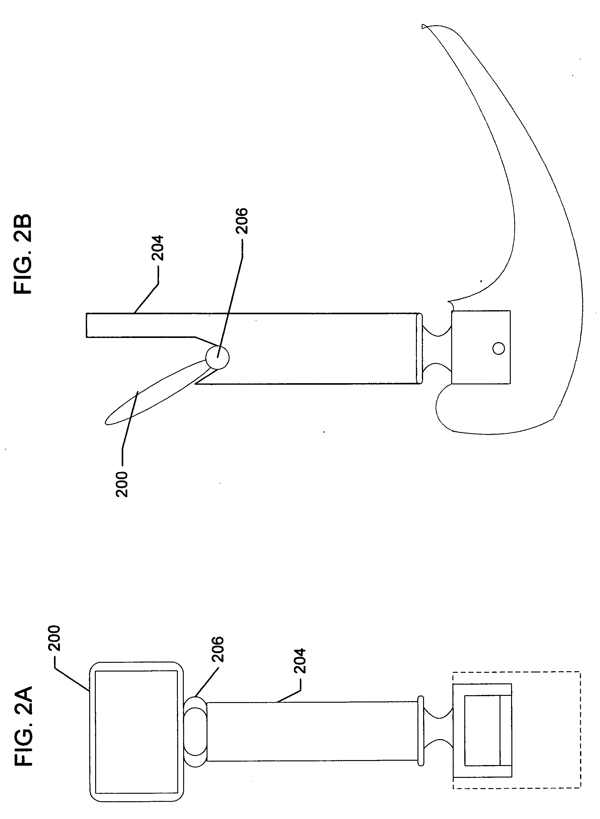
[0012]In an embodiment of the present invention, there is an apparatus for facilitating medical endotracheal intubation, in which an endotracheal tube, hereinafter referred to as the ET tube, is inserted via a patient's oral or nasal cavity. The apparatus includes: a laryngoscope, the laryngoscope configured to be held during use by a first hand of a medical worker having two hands; a visual display device, the visual display device configured to be coupled to the laryngoscope for physical support of the visual display device during use; and an image acquisition device for acquiring imagery for display on the visual display device, a distal end of the image acquisition device configured to be disposed near a distal end of an elongated element, the elongated element configured to be physically moved during use primarily by a second hand of the medical worker, and thereby the distal end of the image acquisition device being configured to be physically moved during use primarily by the second hand, the first and second hands being the two hands of the medical worker, the imagery for helping to visualize, during use, an opening that is a target for insertion of the ET tube.

Problems solved by technology

However, there are many situations in which a lifting of the soft tissues in the oropharynx with a laryngoscope does not provide sufficient visualization of the vocal cords.
The problem typically lies in an inability to see around soft tissues that obstruct the needed view, e.g., including but not limited to some of the following: large tonsils or base of tongue, floppy epiglottis, low lying larynx, retrognathic mandible, excessive soft tissues of the oropharynx and hypopharynx, and the like.
Lack of direct visualization of the larynx provides a dilemma for the medical practitioner performing traditional intubation because there is no way of placing the tip of the ET tube into the trachea with confidence.
The tip of the ET tube may end up erroneously in the blind channel of the pyriform sinuses or in the esophageal inlet.
Such erroneous placement is likely to injure the patient's hypopharynx and laryngeal structures and will lose precious time for oxygen ventilation, with perhaps fatal consequences.
As mentioned above, a blind intubation can cause trauma to the patient's structures and may result in erroneous placement or lost time for ventilation.
Examples from this category generally suffer from at least one of being difficult to use or requiring the presence of certain unwieldy equipment, e.g., certain equipment of a type not normally in-hand during traditional intubation.
A problem with examples from this category is that the distal end of the laryngoscope lacks mobility, and therefore the camera or fiber-optic cable might not be optimally placed and might not actually succeed in providing indirect visualization.
A problem with examples from this category includes substantial departure from the traditional method of intubation and therefore requirement for substantial training of practitioners.

Method used


Image

  • Apparatus and method for imaging-assisted intubation using pre-existing practitioner skill set
  • Apparatus and method for imaging-assisted intubation using pre-existing practitioner skill set
  • Apparatus and method for imaging-assisted intubation using pre-existing practitioner skill set

Examples


Embodiment Construction

[0024]The description above and below and the drawings of the present document refer to examples of currently preferred embodiments of the present invention and also describe some exemplary optional features and / or alternative embodiments. It will be understood that the embodiments referred to are for the purpose of illustration and are not intended to limit the invention specifically to those embodiments. For example, preferred features are, in general, not to be interpreted as necessary features. On the contrary, the invention is intended to cover alternatives, variations, modifications and equivalents and anything that is included within the spirit and scope of the invention.

[0025]Some embodiments of the present invention seek to avoid at least some of the deficiencies of the existing alternative equipment and techniques. The deficiencies, for example, may include but are not limited to one or more of: (1) requiring the presence of certain unwieldy equipment of a type not normall...


PUM


Abstract

An apparatus facilitates indirect visualization of vocal cords during intubation. In one embodiment, the apparatus includes: a laryngoscope, the laryngoscope configured to be held during use by a first hand of a medical worker having two hands; a visual display device, the visual display device configured to be coupled to the laryngoscope for physical support of the visual display device during use; and an image acquisition device for acquiring imagery for display on the visual display device, a distal end of the image acquisition device configured to be disposed near a distal end of an elongated element, the elongated element configured to be physically moved during use primarily by a second hand of the medical worker, and thereby the distal end of the image acquisition device being configured to be physically moved during use primarily by the second hand, the first and second hands being the two hands of the medical worker, the imagery for helping to visualize, during use, an opening that is a target for insertion of the ET tube.

Description

BACKGROUND [0001]In hospital settings or non-hospital settings, intubation of a patient may be required. For example, intubation may be required to insert an endotracheal tube (“ET tube”) into a patient's airway in order to connect an external ventilator for oxygenation. The traditional method of airway intubation includes direct visualization (i.e., seeing) of the larynx including vocal cords. In seeking direct visualization, the practitioner begins by lifting the patient's jaw and tongue base with a laryngoscope and manipulating the head and cervical portion of the neck to position the patient's larynx. This lifting of the soft tissues of the oropharynx (or, back of the throat) and / or epiglottis usually suffices to provide direct visualization of the vocal cords through the oral cavity. The distal tip of the laryngoscope generally includes a light emitter that hopefully illuminates the vocal cords. (In the present document, “distal” and “proximal” are used in reference to the medi...

Claims


Application Information

Patent Timeline
Patent Type & Authority Applications(United States)
IPC IPC(8): A61B1/267
CPCA61B1/00052A61M16/0488A61B1/267
Inventor KIM, TAEHOON
Owner KIM TAEHOON
Why Eureka
Try Eureka