
Machine tool with mist disposal structure

Active Publication Date: 2008-12-25
FANUC LTD
View PDF12 Cites 2 Cited by
  • Summary
  • Abstract
  • Description
  • Claims
  • Application Information

AI Technical Summary

Benefits of technology

[0007]Accordingly, the present invention is intended to prevent a mist produced in a machining area of a machine tool with an air bearing from flowing into the interior of the machine tool.
[0009]Accordingly, the object of the present invention is to improve a dustproof-waterproof structure of drive sections by utilizing air discharged from the air bearing, quickly removing a mist produced in the machining area, and stabilizing a change of temperature that influences the machining accuracy.
[0013]According to the present invention, a machine cover is provided having a sealed structure without a gap, and the internal pressure of the machine tool is increased so that the air discharged from the air bearing can intensively flow from the machine tool interior into the machining area through a space in the labyrinth. The machining area may be provided with an air vent that opens into the atmosphere, whereby a flow of air that is discharged into the atmosphere through the air vent can be created. Thus, the mist produced in the machining area can be prevented from flowing into the machine tool through the labyrinth space.
[0014]Further, the temperatures of the airs supplied to and discharged from the air bearing can be kept constant by stabilizing or keeping the supplied air temperature at the predetermined value by means of the temperature controller.
[0015]Furthermore, a mist collector is connected to the air vent that is disposed inside the machine tool or in the machining area and opens into the atmosphere, whereby the mist produced in the machining area can be sucked in. Thus, the mist in the machining area can be more efficiently removed or prevented from flowing into the machine tool.

Problems solved by technology

Since the non-contact structure inevitably involves voids, however, it is lower in dustproof-waterproof performance than any other bearing structure.

Method used


Image

  • Machine tool with mist disposal structure
  • Machine tool with mist disposal structure
  • Machine tool with mist disposal structure

Examples


Embodiment Construction

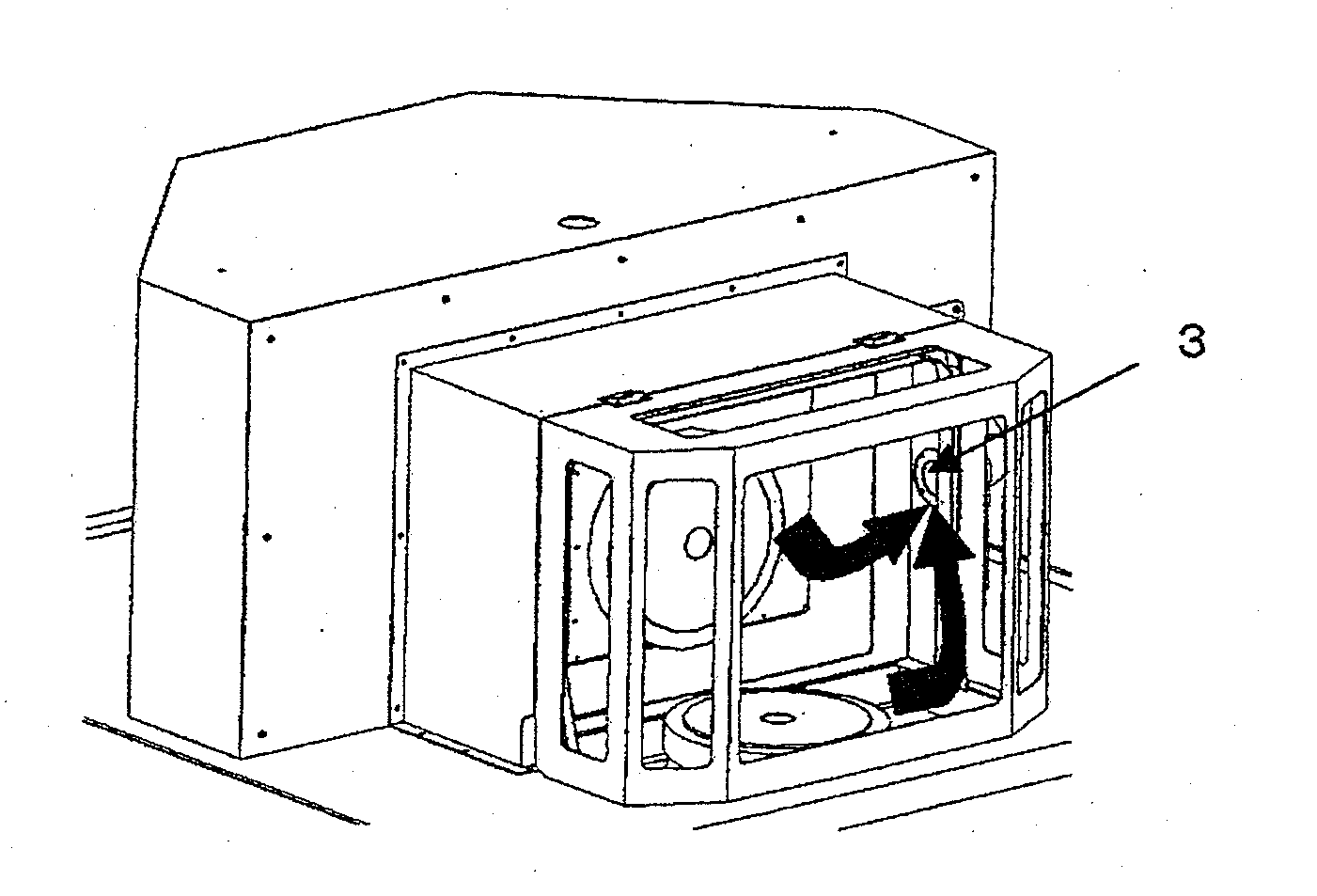
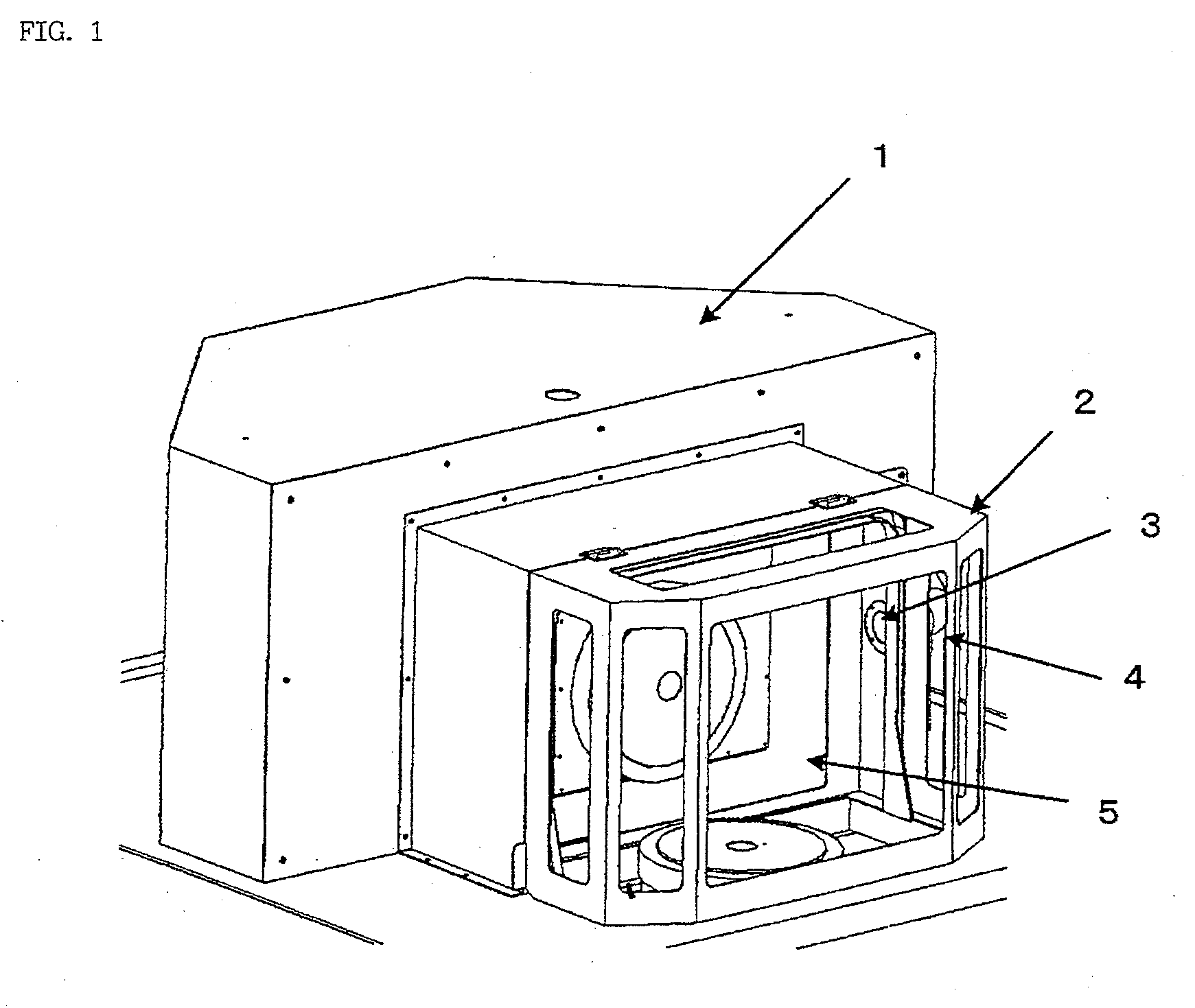
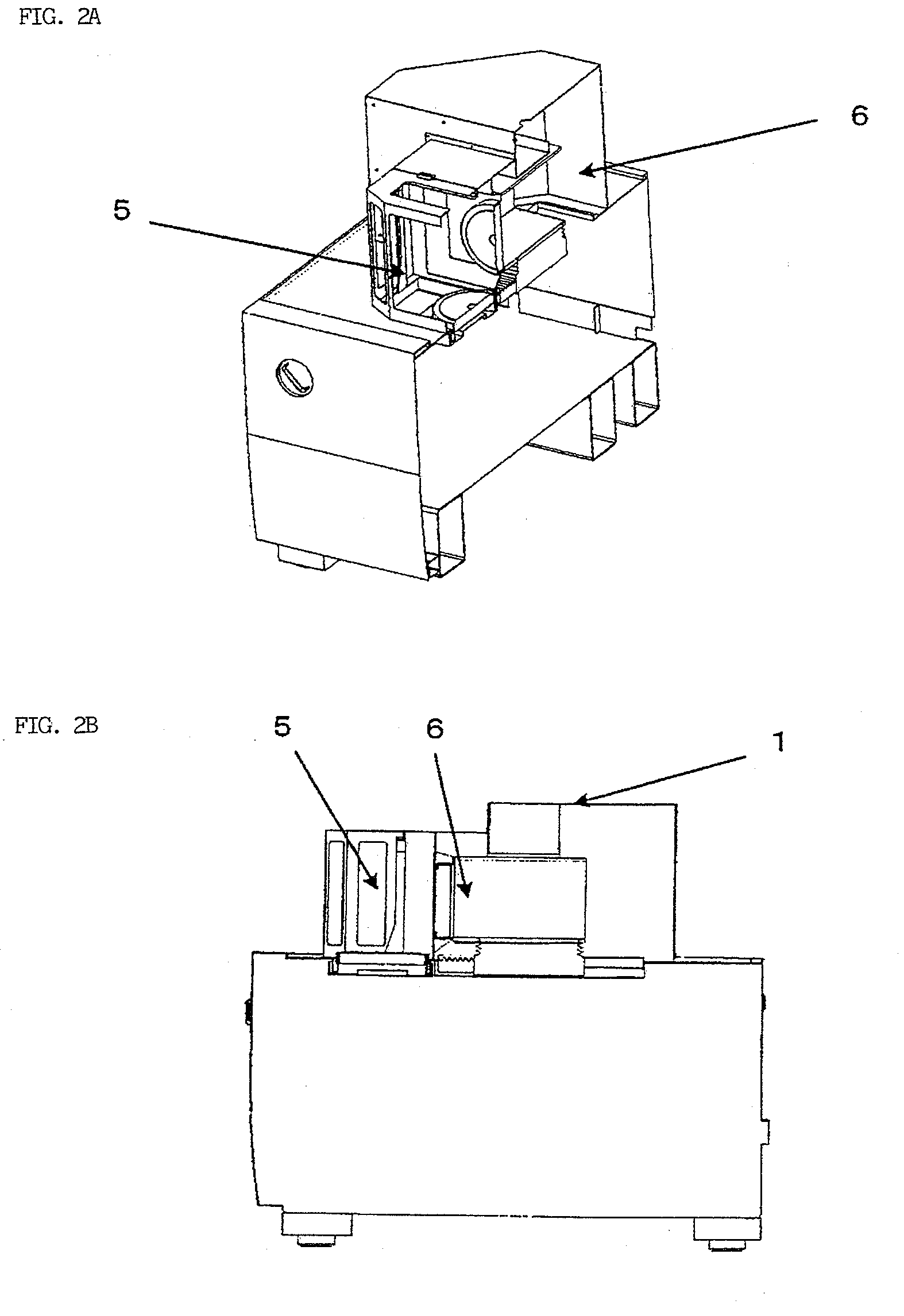
[0028]FIG. 1 shows a part of a machine tool in which a machining area 5 is covered by a cover 2. The machining area cover 2 that covers the machining area 5 is screwed to a machine cover 1, which covers an interior 6 of the machine tool, with the aid of a rubber gasket. The machine tool interior 6 that is covered by the machine cover 1 is loaded with a shaft drive section including an air bearing and a structure that is furnished with the shaft drive section.

[0029]As shown in FIG. 3, rotating shaft drive sections 7 are arranged individually in lower and lateral parts of the machining area 5. An air bearing is used in each of these rotating shaft drive sections 7. The machine tool interior 6 and the machining area 5 are divided by a labyrinth (not shown). The machine cover 1 that covers the machine tool interior 6 has a sealed structure besides the labyrinth such that air in the interior 6 never leaks out of the machine tool. Thus, compressed air supplied to the air bearing is discha...


PUM

PropertyMeasurementUnit
Temperatureaaaaaaaaaa
Areaaaaaaaaaaa

Abstract

An interior of a machine tool and a machining area are divided for communication by a labyrinth. The machining area is covered by a cover. Air discharged from an air bearing flows from the machine tool interior into the machining area through the labyrinth. The cover for the machining area is provided with an exhaust unit for discharging the air from the air bearing or a mist produced in the machining area to the outside of the machine tool.

Description

BACKGROUND OF THE INVENTION[0001]1. Field of the Invention[0002]The present invention relates to a machine tool provided with a mist disposal structure capable of removing a mist in a machining area and preventing the mist from flowing into the interior of the machine tool.[0003]2. Description of the Related Art[0004]In a machine tool, high-accuracy straightness and high rotational accuracy can be realized by the use of an air bearing. The dustproof and waterproof performance of the conventional machine tool using the air bearing can be improved by the use of a labyrinth or several layers of non-contact bellows (e.g., Japanese Patent Application Laid-Open No. 2002-331439). Alternatively, a device for supplying clean air is disposed and used to increase the pressure in the machining area, thereby preventing penetration of a mist (e.g., Japanese Utility Mode Application Laid-Open No. 6-45315). In another arrangement, bearing air delivered from an air bearing is only discharged into th...

Claims


Application Information

Patent Timeline
IPC IPC(8): B01D50/00
CPCB23Q11/0891Y10S55/18
Inventor KAWAI, TOMOHIKOEBIHARA, KENZOOOKI, TAKESHI
Owner FANUC LTD
Learn More