
Piezo-resistive detection resonant device made using surface technologies

Active Publication Date: 2008-12-25
COMMISSARIAT A LENERGIE ATOMIQUE ET AUX ENERGIES ALTERNATIVES
View PDF6 Cites 53 Cited by
  • Summary
  • Abstract
  • Description
  • Claims
  • Application Information

AI Technical Summary

Benefits of technology

[0030]The invention relates to a resonant device for detection in the piezo-resistive plane made using surface technologies on a bulk, characterised in that it comprises a resonator connected to this bulk by at least one embedded portion, wherein excitation means of this resonator and detection means comprise at least one suspended beam type strain gauge made from a piezo-resistive material, in that each strain gauge has at least one common plane with the resonator, and is connected to this resonator at a point situated outside of this at least one embedded portion to increase the stress observed by this strain gauge.

Problems solved by technology

When the sensors are miniaturised, especially for NEMS sensors (“Nano Electro-Mechanical System”), detection becomes a problem:
due to the difficulty in making piezo-resistive gauges for detection with embedded resistors.
this greatly restricts the designs of the sensors, especially for bi-axial integrated sensors, such as for inertia sensors for example,
poor adaptation for sensors made using surface technology,
poor adaptation for “ultra-miniaturised” sensors, such as NEMS sensors, as it is difficult to define, with sufficient accuracy and without adding mechanical stresses due to the metallisations on the test body, the doped and connection zones to make the gauge bridges on beams of just a few tens of nanometres wide.
However such a deposit may create several major disadvantages:
detection outside of the plane, which may be a disadvantage in terms of the design, especially if electrostatic excitation that is isolated from the bulk is desired, in the case of a monocrystalline silicon resonator for example.
However, it does not allow high levels of sensitivity and stability to be obtained.

Method used


Image

  • Piezo-resistive detection resonant device made using surface technologies
  • Piezo-resistive detection resonant device made using surface technologies
  • Piezo-resistive detection resonant device made using surface technologies

Examples


first embodiment

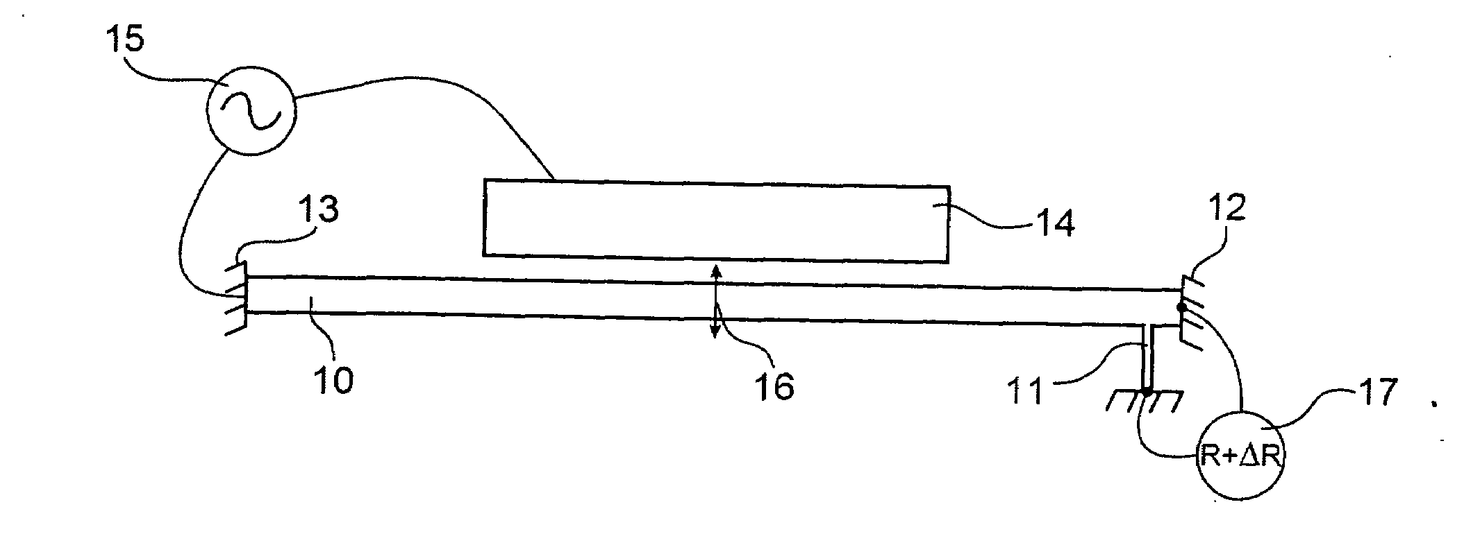
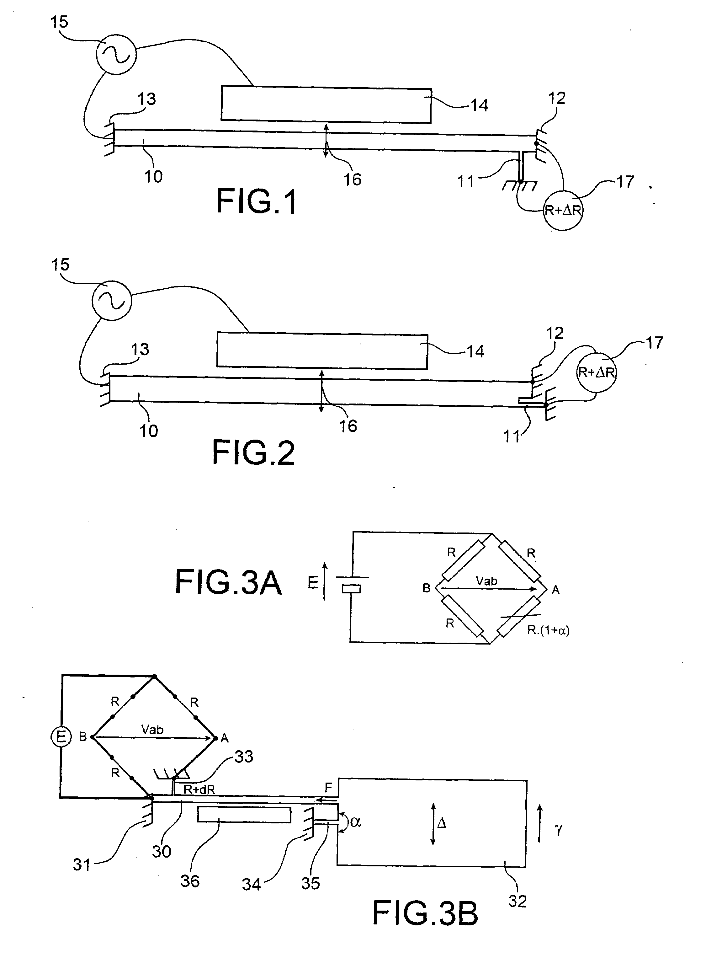
[0058]FIG. 1 illustrates the resonator type of the device of the invention.

second embodiment

[0059]FIG. 2 illustrates the resonator type of the device of the invention.

[0060]FIGS. 3A and 3B illustrate a first embodiment of the sensor type of the device of the invention.

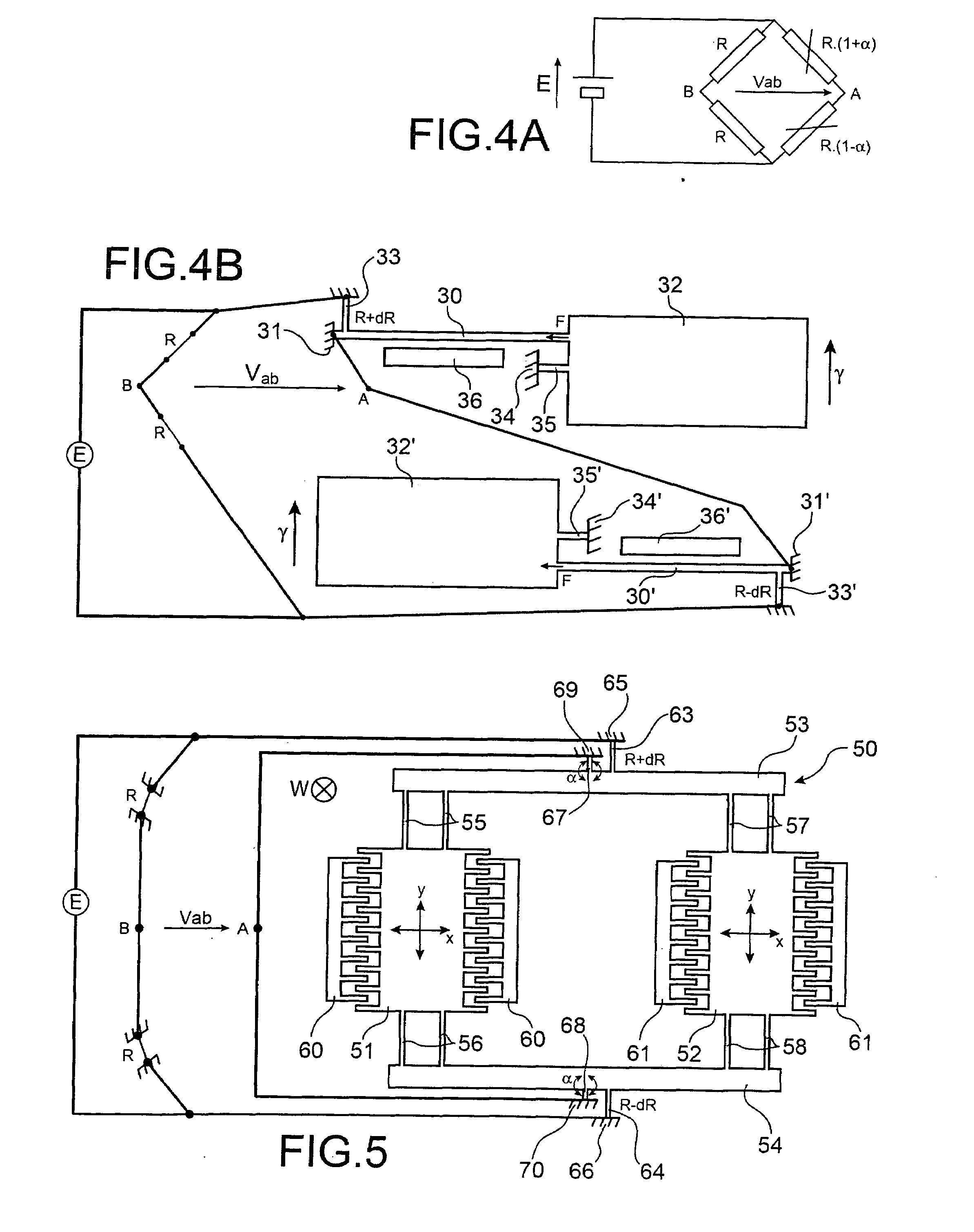
[0061]FIGS. 4A and 4B illustrate a second embodiment of the sensor type of the device of the invention.

third embodiment

[0062]FIG. 5 illustrates the sensor type of the device of the invention.

[0063]FIGS. 6A to 6C and 6A′ to 6C′ illustrate the steps of a first example of an embodiment, respectively in cross sectional and top views.

[0064]FIGS. 7A to 7F and 7A′ to 7F′ (there is no FIG. 7E′) illustrate the steps of a second example of an embodiment, respectively in cross sectional and top views.

[0065]FIGS. 8A to 8G and 8A′ to 8G′ (there is no FIG. 8B′) illustrate the manufacturing steps of an embodiment of the device of the invention, respectively in cross sectional and top views.

[0066]FIG. 9 illustrates another embodiment of the device of the invention.


PUM


Abstract

This invention relates to a resonant device with detection in the piezo-resistive plane made using surface technologies on a bulk, which comprises a resonator connected to this bulk by at least one embedded portion, means of exciting this resonator and detection means comprising at least one suspended beam type strain gauge made from piezo-resistive material, in which each strain gauge has a common plane with the resonator, and is connected to this resonator at a point situated outside of this at least one embedded portion to increase the stress observed by this strain gauge.

Description

CROSS REFERENCE TO RELATED APPLICATIONS or PRIORITY CLAIM[0001]This application claims priority to French Patent Application No. 07 55992, filed Jun. 25, 2007.TECHNICAL FIELD[0002]The invention relates to a piezo-resistive detection resonant device made using surface technologies.[0003]The field of the invention is particularly that of silicon micro / nano-sensors, accelerometers, gyrometers and force sensors.STATE OF THE PRIOR ART[0004]To analyse the state of the prior art, we will successively analyse that of resonant sensors and that of piezo-resistive sensors.Resonant Sensors[0005]In the prior art, resonant sensors may be made:[0006]either using volume technology, in which the sensitive element of the sensor is made from the entire thickness of the bulk, generally by using wet etching of silicon or quartz,[0007]or using surface technology, in which the silicon bulk is only machined on a fraction of its thickness, typically from a few micrometres to several tens of micrometres in t...

Claims


Application Information

Patent Timeline
IPC IPC(8): G01P15/12G01L1/22G01C19/56
CPCB81B3/0086B81B2201/0235B81B2201/0242B81B2201/0264B81B2201/0271H03H9/02259G01C19/5755G01C19/5769G01L1/183G01P15/0802G01P15/097G01C19/574
Inventor ROBERT, PHILIPPE
Owner COMMISSARIAT A LENERGIE ATOMIQUE ET AUX ENERGIES ALTERNATIVES
Features
  • Generate Ideas
  • Intellectual Property
  • Life Sciences
  • Materials
  • Tech Scout
  • Unparalleled Data Quality
  • Higher Quality Content
  • 60% Fewer Hallucinations
Learn More