
Mechanically actuated thermal switch

a mechanical actuator and thermal switch technology, applied in the field of thermal switches, can solve the problems of not being able to initiate thermal transfer on command or be tuned to control the thermal transfer rate, switches will not work in an environment or system, and types of thermal switching means will not work, so as to achieve the effect of controlling the radiative thermal transfer ra

Active Publication Date: 2008-12-25
THE BOEING CO
View PDF12 Cites 9 Cited by
  • Summary
  • Abstract
  • Description
  • Claims
  • Application Information

AI Technical Summary

Benefits of technology

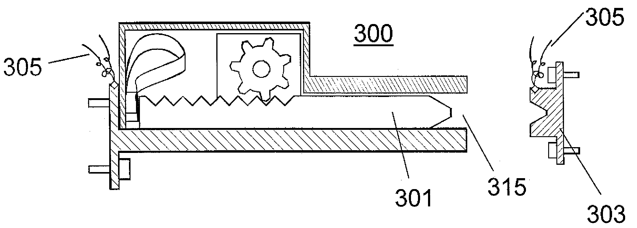
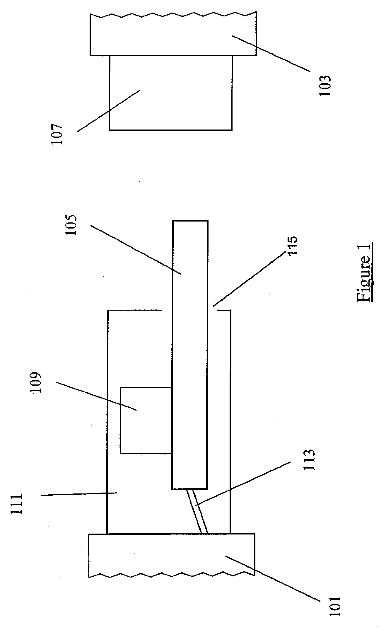
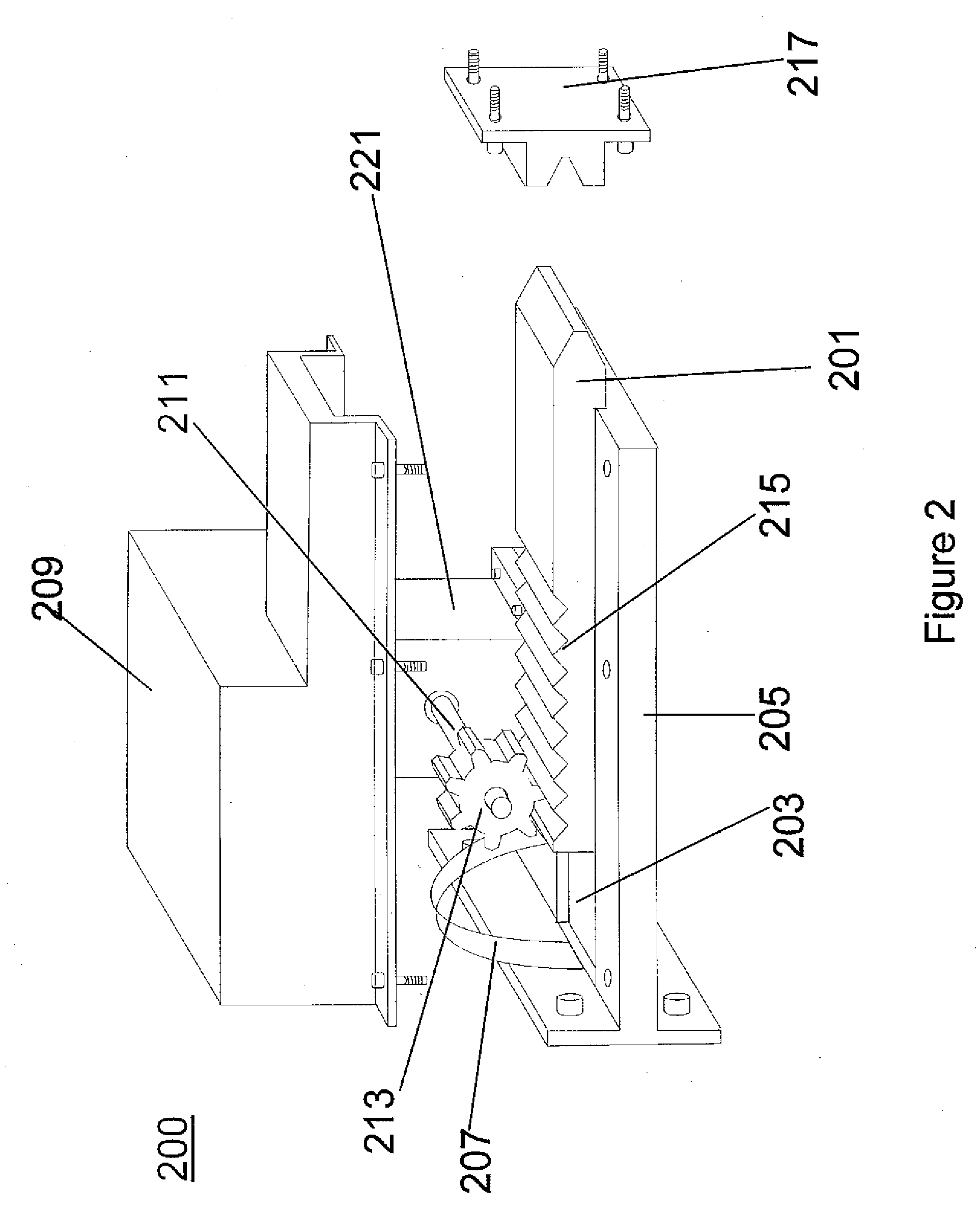
[0005]In various embodiments, methods may include moving the first one or more thermally conductive members to be placed within a sufficient proximity to the second one or more members to facilitate a selected radiative thermal transfer rate between the first and second structures via the first and second one or more thermally conductive members. Radiative thermal transfer may be slower than other forms of thermal transfer such as, for example, conductive thermal transfer. Therefore, depending on a desired rate of thermal conductivity, radiative thermal transfer may be advantageous.
[0019]In various embodiments, the rotating plate(s) may be further adapted to be rotatable so that it contacts a thermally conductive stop attached to the second structure, thereby advantageously facilitating a conductive thermal transfer between the first and second structures in addition to the radiative thermal transfer.

Problems solved by technology

A significant limitation of these thermal switches is that they can not initiate thermal transfer on command or be tuned to control the rate of thermal transfer.
For a system in which the desired thermal transfer between structures in the system is not known when the system is designed or manufactured, these types of thermal switching means will not work.
Also, because these thermal switches can not be commanded to initiate or suspend thermal transfer, or be dynamically tuned to alter the rate of thermal transfer, these switches will not work in an environment or system where the thermal transfer or flow requirements between elements may change over time.

Method used


Image

  • Mechanically actuated thermal switch
  • Mechanically actuated thermal switch
  • Mechanically actuated thermal switch

Examples


Embodiment Construction

[0028]In the following detailed description, reference is made to the accompanying drawings which form a part hereof and in which is shown, by way of illustration, embodiments of the disclosure. It is to be understood that other embodiments may be utilized and structural or logical changes may be made without departing from the scope of the disclosure. Therefore, the following detailed description is not to be taken in a limiting sense, and the scope of embodiments in accordance with the disclosure is defined by the appended claims and their equivalents.

[0029]Various operations may be described as multiple discrete operations in turn, in a manner that may be helpful in understanding various embodiments; however, the order of description should not be construed to imply that these operations are order dependent.

[0030]The description may use perspective-based descriptions such as up / down, back / front, and top / bottom. Such descriptions are merely used to facilitate the discussion and ar...


PUM


Abstract

Methods and apparatuses for causing thermal transfer between two structures on command including responding, by a thermal switch, to a command signal by moving a first set of one or more thermally conductive members into a position adjacent to a second set of one or more thermally conductive members, the first and second one or more thermally conductive members having thermally conductive contacts with the first and second structures, respectively.

Description

FIELD OF THE INVENTION[0001]Embodiments of the disclosure relate to thermal switches, specifically switches for transferring heat and / or tuning the rate of heat transfer between two structures on command.BACKGROUND OF THE INVENTION[0002]There are many thermal switching means to transfer heat between structures, such as in cryogenic refrigeration systems, also known as cryocoolers. These means are passive and operate by isolating the cryocooler and associated hardware from outside heat leaks. These devices depend on principles of thermal expansion of materials to create or tear down a thermally conductive path between structures. Thus, when a desired temperature is reached, a conductive material either expands or contracts thereby connecting or isolating a structure to be cooled or heated. A significant limitation of these thermal switches is that they can not initiate thermal transfer on command or be tuned to control the rate of thermal transfer. For a system in which the desired t...

Claims


Application Information

Patent Timeline
Patent Type & Authority Applications(United States)
IPC IPC(8): F28F27/00
CPCF28F13/00F28F2013/008
Inventor GRAYSON, GARY D.HENLEY, MARK W.
Owner THE BOEING CO
Learn More