Thermal cutter

Inactive Publication Date: 2008-12-25
KOMATSU IND CORP
View PDF39 Cites 15 Cited by
  • Summary
  • Abstract
  • Description
  • Claims
  • Application Information

AI Technical Summary

Benefits of technology

[0010]As described above, with a thermal cutting device, various techniques are per se

Problems solved by technology

Heisei 9-57438, there is a problem with regard to the cost entailed, since it is necessary to cover over the entire upper surface of the main table.
Heisei 7-136767, since the hood is provided over the plasma torch itself, there is the problem that this technique cannot be applied to long term use, since, during the thermal cutting process, the hood experiences the influence of heat and the like.
Heisei 7-155991, there is the problem that a substantial manufacturing cost is incurred, since it is necessary to provide a mechanism for shifting the hood itself.
Moreover there is the problem that if, due to th

Method used


Image

  • Thermal cutter
  • Thermal cutter
  • Thermal cutter

Examples


Embodiment Construction

[0045]Embodiments of the present invention will now be explained with reference to the drawings. It should be understood that the embodiments described below are not to be considered as being limitative in any way of the scope of the present invention, which is to be defined solely by the appended Claims; and the combination of all of the characteristics explained in the description of the embodiments is not to be considered as being essential to the implementation of the present invention.

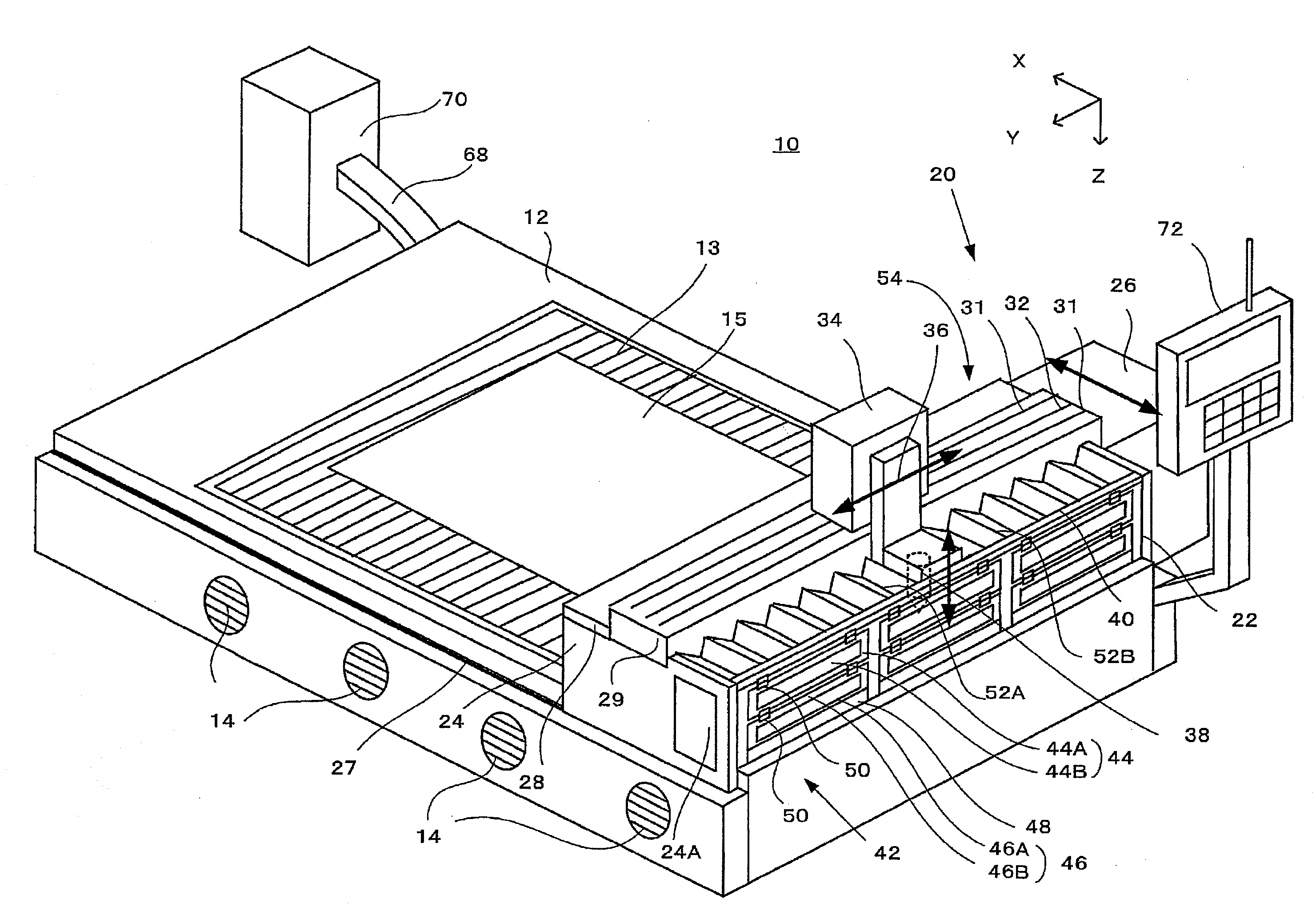
[0046]According to the embodiments explained below, along with it being possible to reduce the noise due to the thermal cutter, it is also possible to perform maintenance simply and easily. Furthermore, according to the embodiments explained below, along with it being possible effectively to collect the fumes which are generated during thermal cutting with the cutter, it is also possible to reduce the negative influence exerted upon the thermal cutter due to the fumes.

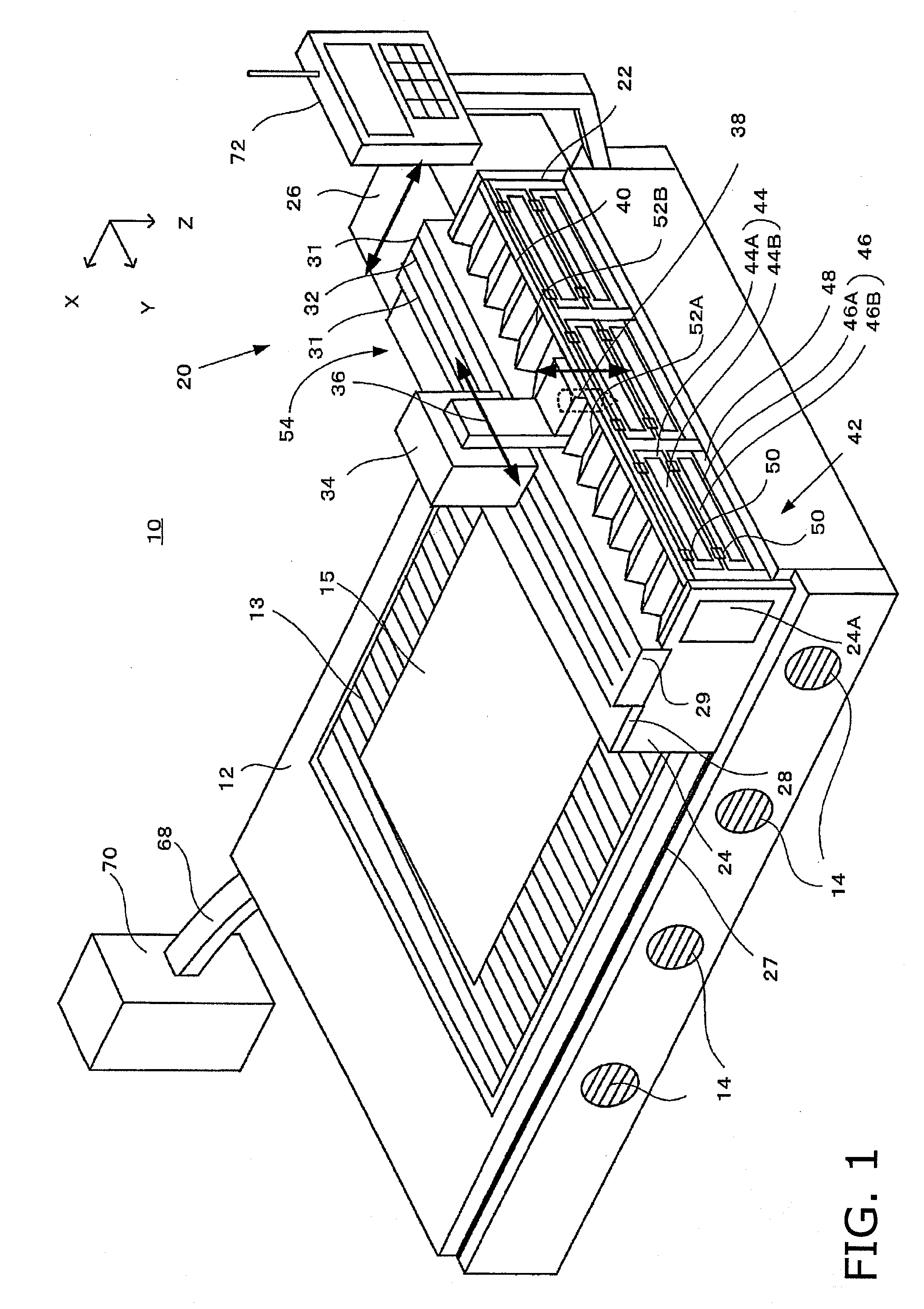
[0047]FIG. 1 is a perspective...


PUM

PropertyMeasurementUnit
Lengthaaaaaaaaaa
Electrical resistanceaaaaaaaaaa
Areaaaaaaaaaaa

Abstract

A thermal cutter for cutting with heat a board mounted upon a table having an internal space includes a plurality of walls and a sound absorbent material. The walls are disposed in the internal space of the table to partition a plurality of exhaust chambers with each of the exhaust chambers having an aperture that opens towards a side on which the board is mounted. The sound absorbent material is provided to at least a portion of at least one of the walls, the sound absorbent material being removably coupled to the table.

Description

CROSS-REFERENCE TO RELATED APPLICATIONS[0001]This application claims priority to Japanese Patent Application Nos. 2007-165542 and 2008-144659. The entire disclosure of Japanese Patent Application Nos. 2007-165542 and 2008-144659 are hereby incorporated herein by reference.BACKGROUND OF THE INVENTION[0002]1. Field of the Invention[0003]The present invention relates to a thermal cutter for thermally cutting a board which is mounted upon a table, such as, for example, a plasma cutter, a laser cutter, a gas cutter, or the like.[0004]2. Background Information[0005]A table for a thermal cutter of this type is disclosed in Japanese Laid-Open Patent Publication No. 2003-136248, etc. Typically, a large number of planks (long and narrow boards) are arranged on edge upon the upper portion of a table for this kind of thermal cutter, with fixed intervals between them, so that the board which is to be cut can be conveniently mounted thereupon. With this type of thermal cutter, when performing the...

Claims


Application Information

Patent Timeline
IPC IPC(8): B23H9/00
CPCB23K7/002B23K7/10B23K37/0461B23K26/1405B23K26/422B23K10/00B23K26/702B23K26/142
Inventor YAMAGUCHI, YOSHIHIROOHNISHI, SATOSHI
Owner KOMATSU IND CORP
Why Eureka
Try Eureka