Interleaved power factor correction pre-regulator phase management circuitry

a power factor and pre-regulator technology, applied in the direction of electric variable regulation, process and machine control, instruments, etc., can solve the problems of only observed efficiency improvement, increased switching loss, and reduced light load efficiency, so as to improve the efficiency of power converters and reduce the effect of light power loads

Active Publication Date: 2008-12-25
TEXAS INSTR INC
View PDF18 Cites 24 Cited by
  • Summary
  • Abstract
  • Description
  • Claims
  • Application Information

AI Technical Summary

Benefits of technology

[0011]Methods for power factor correction (PFC) and for improving efficiency of a power converter at lighter power loads are disclosed. Also disclosed are power converters and phase management circuitry for power converters. The power converter includes a first PFC pre-regulator that is interleaved with at least one additional PFC pre-regulator, and a downstream step down converter. The phase management circuitry is structured and arranged to measure the average input power downstream of the front end, which is to say at the step down converter. The average cur...

Problems solved by technology

Efficiency improvements using interleaved techniques, however, are only observed at higher power levels where conduction losses dominate over switching losses.
However, this technique increases parasitic switch/field-effect tran...

Method used


Image

  • Interleaved power factor correction pre-regulator phase management circuitry
  • Interleaved power factor correction pre-regulator phase management circuitry
  • Interleaved power factor correction pre-regulator phase management circuitry

Examples


examples

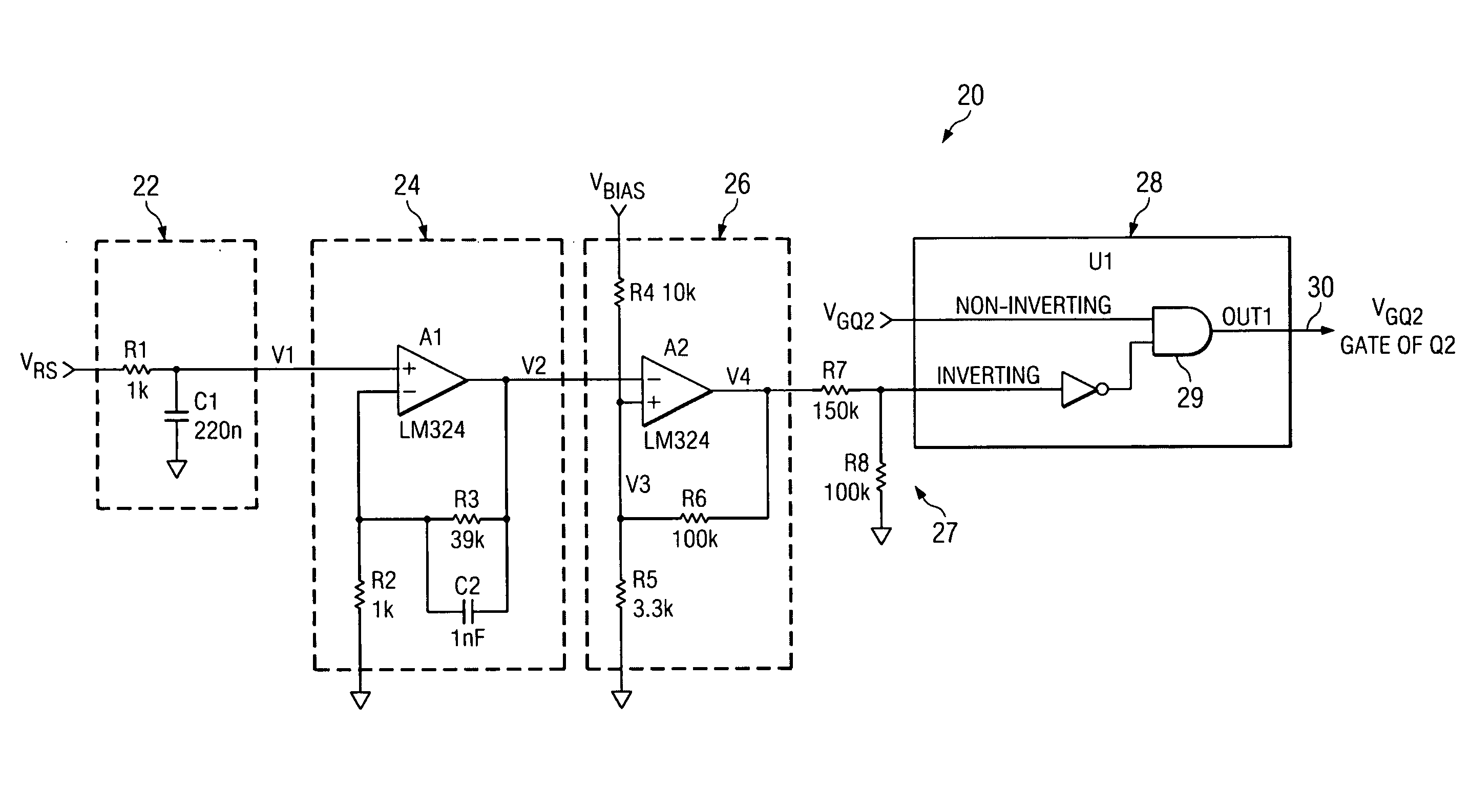
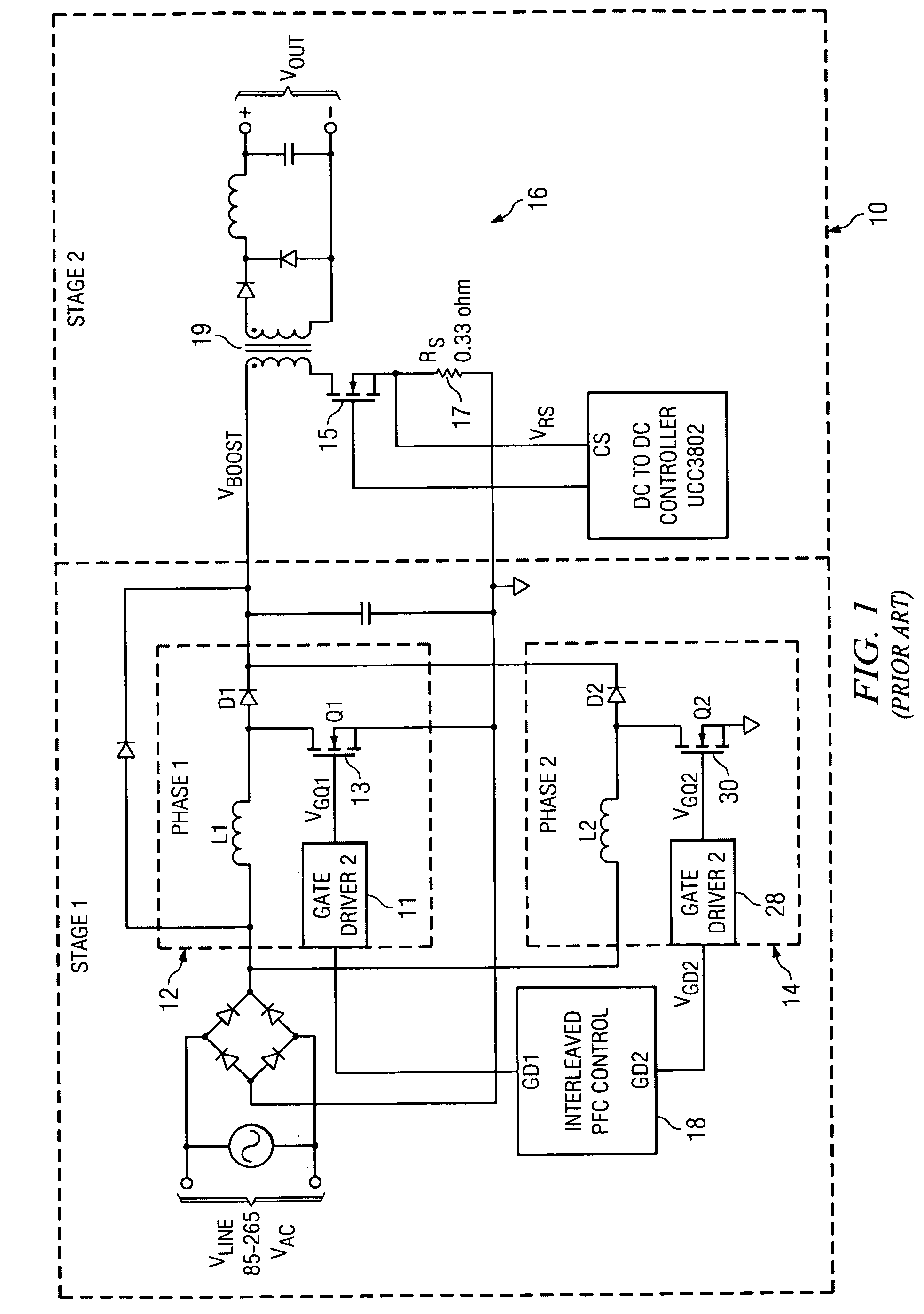
[0027]A power converter 10 and phase management circuitry 20 therefor were evaluated in a 250 W application in which the boost voltage (VBOOST) was 390V. The step down converter 16 was theoretically switching at 100 kHz. The current sense resistor 17 of the step down converter 16 was arbitrarily established at 0.33 ohms(Ω). The bias voltage (VBIAS) was set to 12V.

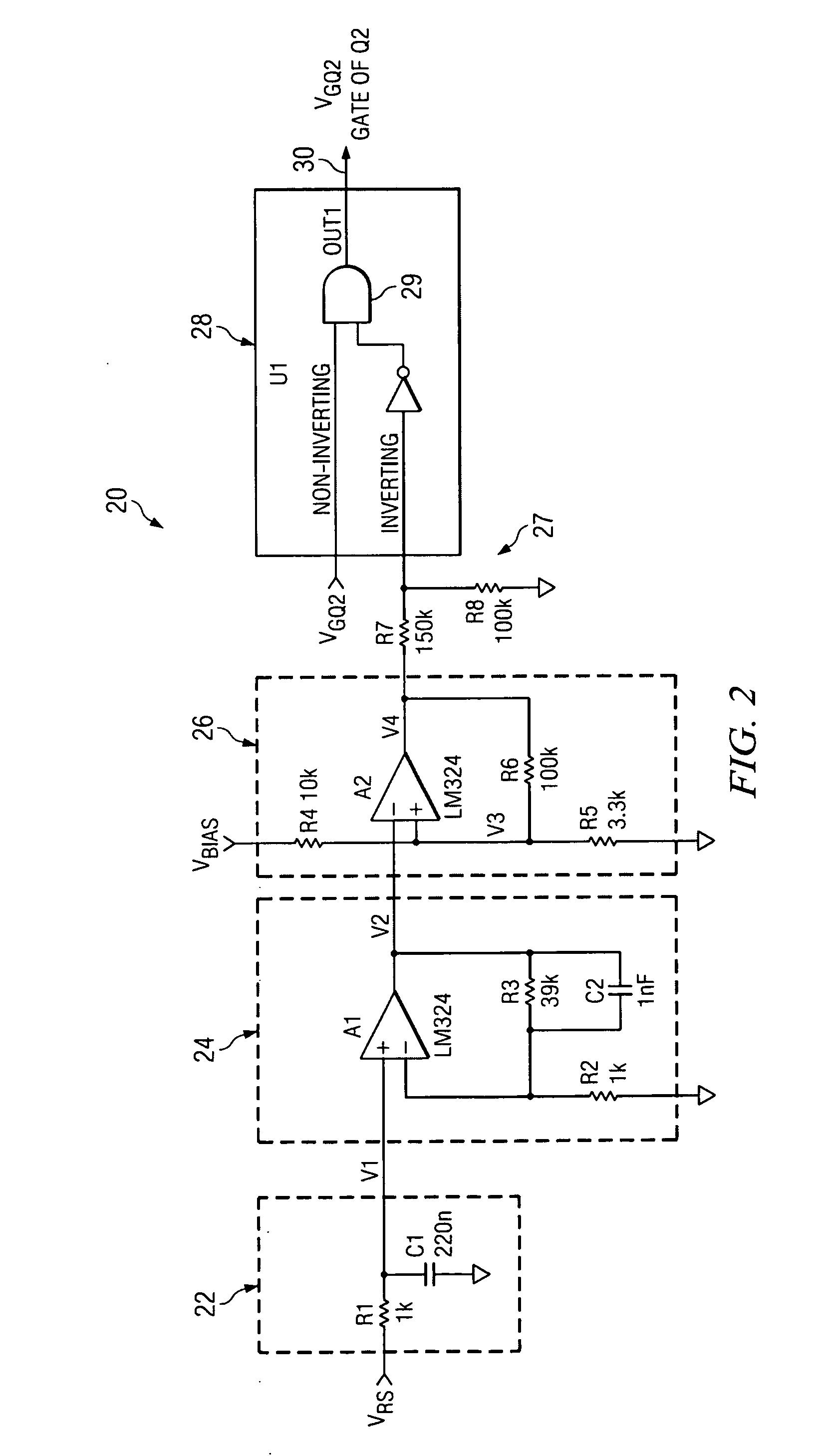
[0028]The phase management circuit 20 was programmed to turn OFF the second (Phase 2) PFC pre-regulator 14 when the power supply is operating at less than 29% of the power converter's rated power and to turn ON the second (Phase 2) PFC pre-regulator 14 when the step down converter 16 is operating at greater than 32% of the power supply's rated power.

[0029]As shown in the calculations below, resistive element R3 of the amplifying unit 24 is sized to amplify the average current sense signal and, moreover, is selected so that gained up average current sense signal (V2) will operate between 0 and 10V. In order for the circuitry...


PUM


Abstract

Methods for power factor correction (PFC) and for reducing conduction losses and switching losses in a power converter as well as the power converter and phase management circuitry for the power converter. The power converter includes a first PFC pre-regulator interleaved with at least one additional PFC pre-regulator, and a step down converter. The average input power is measured downstream of the front end at the step down converter and the average current sense signal is compared to a reference voltage. Each additional PFC pre-regulator is disable when output power generated by the front end is less than a first pre-designated rated power level and each additional PFC pre-regulator is enabled when the output power is greater than a second pre-designated rated power level.

Description

CROSS REFERENCE TO RELATED APPLICATIONS[0001]This patent application is a continuation-in-part of U.S. patent application Ser. No. 12 / 133,080 of the same title filed on Jun. 4, 2008 and claims priority from U.S. Provisional Patent Application No. 60 / 941,844 also of the same title filed on Jun. 4, 2007.STATEMENT REGARDING FEDERALLY SPONSORED RESEARCH OR DEVELOPMENT[0002]Not ApplicableBACKGROUND OF THE INVENTION[0003]Interleaved power factor correction techniques are being used, primarily, to reduce conduction losses in connection with power factor correction (PFC) pre-regulators and to increase power densities by reducing total inductor magnetic volume. Interleaving PFC pre-regulators, in which two or more PFC pre-regulators are operated out-of-phase, is commonly employed in applications such as—for the purpose of illustration and not limitation—power supplies for personal computers, computer server power supplies, and in industrial AC to DC power conversion.[0004]Efficiency improvem...

Claims


Application Information

Patent Timeline
IPC IPC(8): H02M7/217
CPCH02M1/4225H02M3/33515Y02B70/126H02M2003/1586Y02B70/10H02M3/1586
Inventor O'LOUGHLIN, MICHAEL J.
Owner TEXAS INSTR INC
Why Eureka
Try Eureka