
Fingerprint image forming apparatus, finger movement amount calculation method, and fingerprint image forming method

Active Publication Date: 2008-12-25
MITSUMI ELECTRIC CO LTD
View PDF8 Cites 42 Cited by
  • Summary
  • Abstract
  • Description
  • Claims
  • Application Information

AI Technical Summary

Benefits of technology

[0010]Embodiments of the present invention provide a fingerprint image forming apparatus, a finger movement amount calculation method, and a fingerprint image forming method that solve or reduce one or more problems caused by the limitations and disadvantages of the related art.

Problems solved by technology

One problem with a fingerprint reading system using a line sensor is that overlaps between lines of image data vary depending on the speed of a finger moving over the line sensor.
Such variation in the length of a fingerprint image, for example, reduces the reliability of a personal identification system using fingerprints.
One disadvantage of the configuration disclosed in patent document 2 is that it requires a rather large storage area to store lines of image data and therefore is not suitable for a small embedded system.

Method used


Image

  • Fingerprint image forming apparatus, finger movement amount calculation method, and fingerprint image forming method
  • Fingerprint image forming apparatus, finger movement amount calculation method, and fingerprint image forming method
  • Fingerprint image forming apparatus, finger movement amount calculation method, and fingerprint image forming method

Examples


Embodiment Construction

[0019]Preferred embodiments of the present invention are described below with reference to the accompanying drawings.

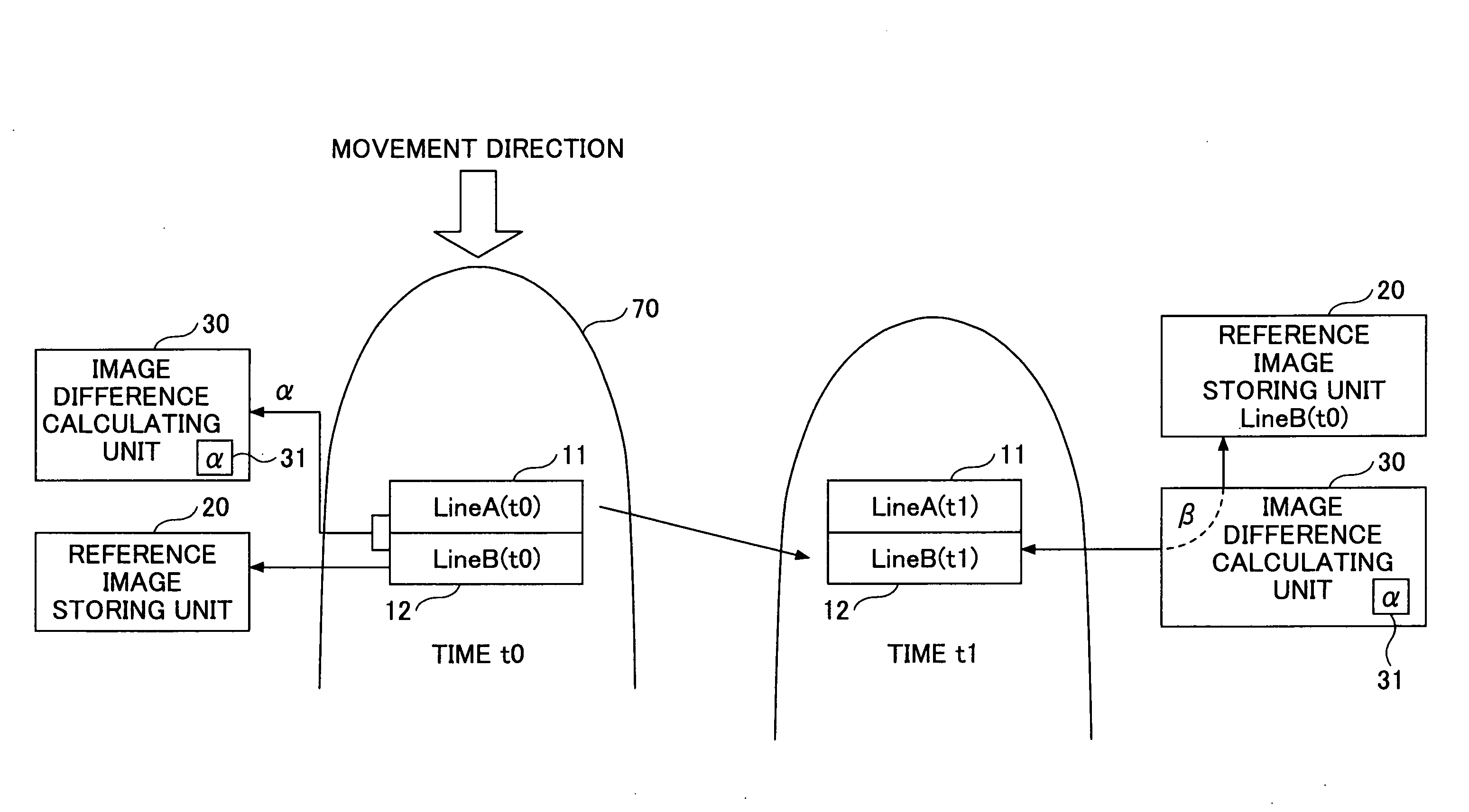
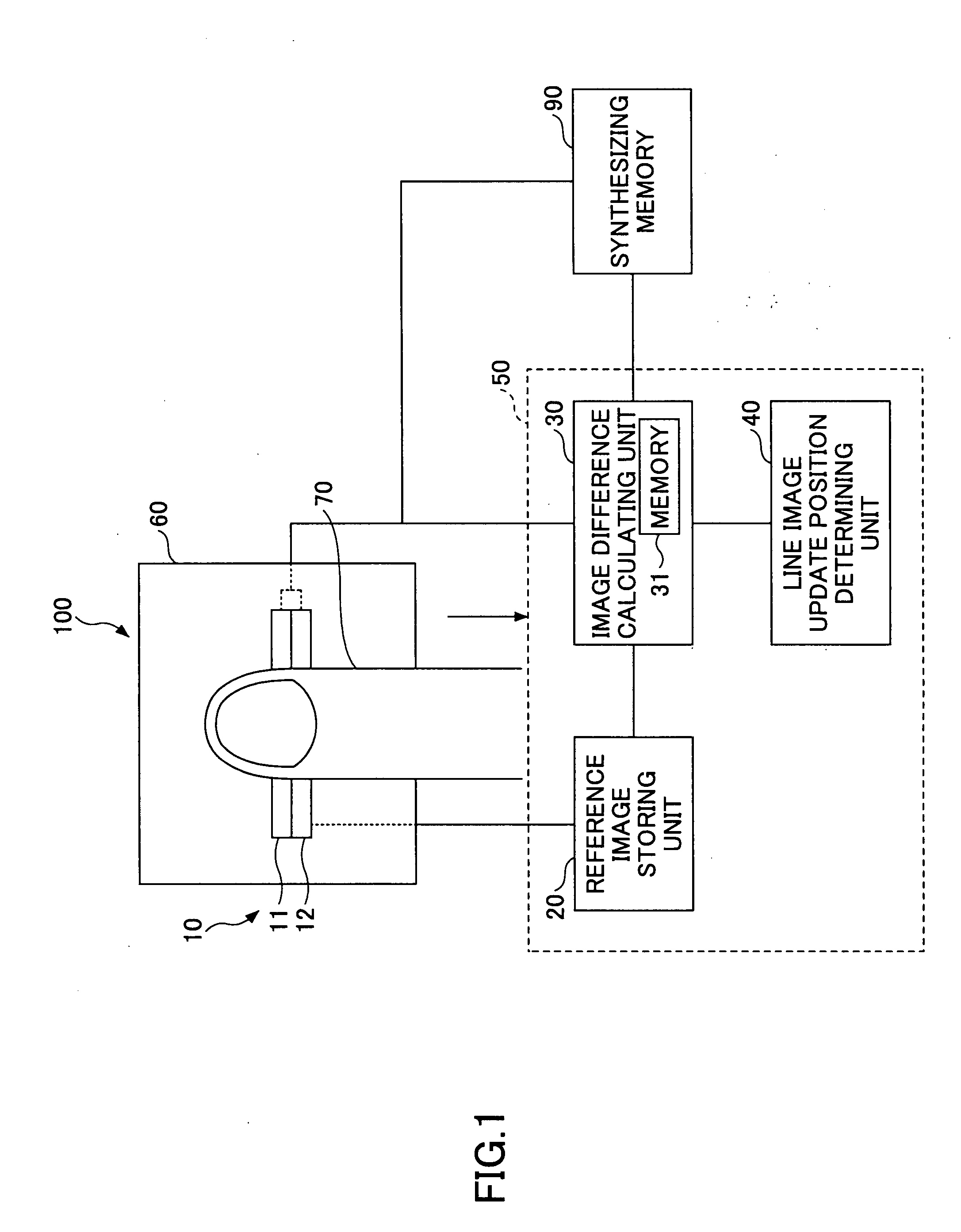
[0020]FIG. 1 is a schematic diagram illustrating a fingerprint image forming apparatus 100 according to an embodiment of the present invention. As shown in FIG. 1, the fingerprint image forming apparatus 100 includes a partial sensor 10 and an arithmetic and control unit 50. The arithmetic and control unit 50 includes a reference image storing unit 20, an image difference calculating unit 30, and a line image update position determining unit 40 (may also be called a partial image update position determining unit). The arithmetic and control unit 50 may include various arithmetic units similar to those of a computer. The fingerprint image forming apparatus 100 may also include a support 60 for holding the partial sensor 10. Further, the fingerprint image forming apparatus 100 may include a synthesizing memory 90 for combining partial images and thereby generating an en...


PUM


Abstract

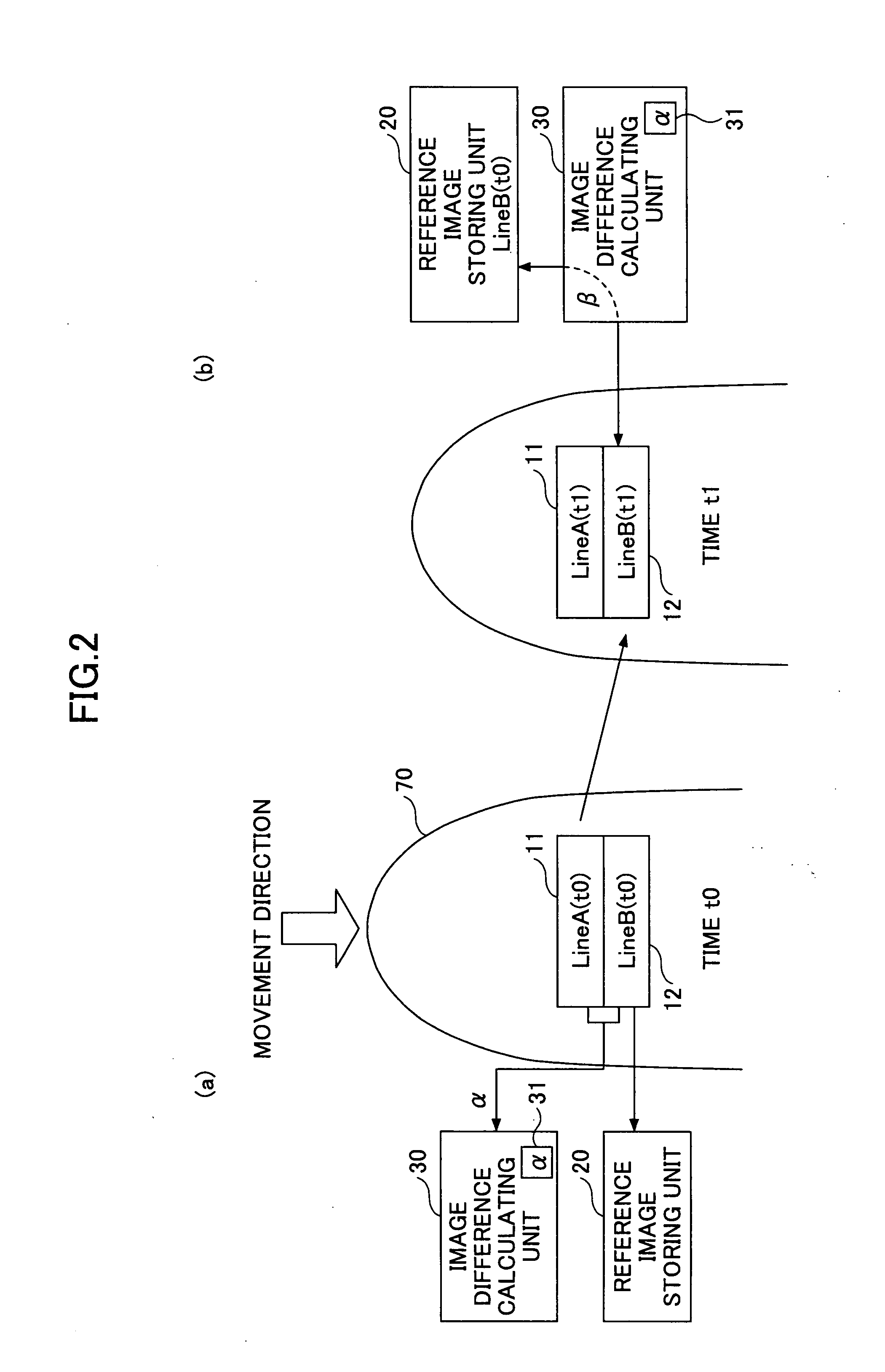
A disclosed apparatus for forming a fingerprint image includes a partial sensor configured to obtain partial images of a fingerprint of a finger moving over the partial sensor; a reference image storing unit configured to store a reference partial image; and an image difference calculating unit configured to calculate a reference image difference between the reference partial image and a first partial image, to calculate a current image difference between the reference partial image and a second partial image, to calculate an amount of movement and / or a position of the finger based on a ratio of the current image difference to the reference image difference, and to store the second partial image and / or the first partial image as parts of the fingerprint image to be formed if the amount of movement and / or the position of the finger is equal to or greater than a predetermined value.

Description

BACKGROUND OF THE INVENTION[0001]1. Field of the Invention[0002]The present invention generally relates to a fingerprint image forming apparatus, a finger movement amount calculation method, and a fingerprint image forming method. More particularly, this invention relates to a fingerprint image forming apparatus including two line sensors, and a finger movement amount calculation method and a fingerprint image forming method used for the fingerprint image forming apparatus.[0003]2. Description of the Related Art[0004]There is a conventional fingerprint reading system that includes a sensor having a surface area smaller than that of a finger. Such a fingerprint reading system reads a fingerprint of a finger moving over the sensor portion by portion and reconstructs the image of the fingerprint from the read partial images (see, for example, patent document 1). A sensor that reads a fingerprint portion by portion is generally smaller than a two-dimensional sensor that can obtain an en...

Claims


Application Information

Patent Timeline
IPC IPC(8): G06K9/00
CPCG06K9/00026G06V40/1335
Inventor TAZOE, NAOKI
Owner MITSUMI ELECTRIC CO LTD
Learn More