Member mounting structure

a mounting structure and member technology, applied in the direction of couplings, rod connections, manufacturing tools, etc., can solve the problems of affecting the workability of mounting screws, so as to prevent the occurrence of defective production, facilitate and rapid performance, and prevent the effect of defective production

Inactive Publication Date: 2008-12-25
TOYODA IRON WORKS CO LTD +1
View PDF4 Cites 7 Cited by
  • Summary
  • Abstract
  • Description
  • Claims
  • Application Information

AI Technical Summary

Benefits of technology

[0020]In the member mounting structure according to the first aspect of the present invention, the second member is provided with the positioning hole fitted to the outer peripheral side of the boss to be positioned relative thereto. The facing surface of the second member which faces with the first member is formed into a flat surface. Thus, by performing mutual positional alignment with the flat facing surface slidably-contacted with the tip end of the boss, the positioning hole can be fitted to the boss to be positioned relative thereto readily.
[0021]Also, on the surface opposite side to the flat facing surface, the tubular portion is disposed to be fitted to the boss, in other words, the positioning hole disposed at the tubular portion and the boss are fitted together. The positioned state is maintained well by the fitting between the tubular portion and the boss. Consequently, the fastening work of screwing the mounting screw into the screw fastening hole of the boss can be performed readily and rapidly, so that the second member is integrally fixed to the first member. Because positional alignment (positional adjustment) can be performed readily, and the fastening work of the mounting screw can be performed readily, so that the member mounting work can be automated.
[0022]Meanwhile, because of the fitting between the boss and the tubular portion, firstly, fastening the mounting screw with the second member ridden on the boss becomes difficult, thus preventing occurrence of the defective production to thereby improve the yield. Secondly, as long as the boss is partially located within the positioning hole, the tubular portion is completely fitted to the boss and is fixed thereto at the predetermined position as the mounting screw is screwed, a high mounting position precision (aligning quality) is always obtained, regardless of deformation, positional deviation, etc., of the respective portions.
[0023]In the second aspect of the present invention, the positioning hole is formed to penetrate through the tubular portion. In addition, by the fitting of the tubular portion to the boss, the flat facing surface is brought into contact with the first member, and the mounting screw is screwed into the screw fastening hole of the boss in this state. Because the head of the mounting screw engages with the tip end surface of the tubular portion to press and to fix the flat facing surface against and to the first member, visual recognition of the screw fastening hole is facilitated. Thus, the screw fastening work can be performed more readily. Also, the second member is simple in the structure, can be arranged inexpensively, and can be made of the resin as in the fifth aspect of the present invention.
[0024]In the third aspect of the present invention, the positioning hole has an inclined surface of which inner wall surface is inclined toward a center line as it goes from the side of the flat facing surface to the side of the tip end of the tubular portion. The area of the opening at side of the flat facing surface is made large, and the aligning work during fitting of the positioning hole relative to the boss is facilitated further. Also, the play existed between the boss and the positioning hole is selected small, so that the aligning of them can be performed at high precision. Thus, the mounting positioning precision of the second member relative to the first member can be improved further.
[0025]In the fourth aspect of the present invention, the plurality of reinforcing ribs are disposed axially on the outer peripheral surface of the boss, and the positioning hole of the second member is fitted to the outer peripheral side of the plurality of reinforcing ribs. Therefore, the aligning of slits, which was necessary in FIG. 5, is not necessary in the present invention. The positioning hole can be fitted readily relative to the boss to perform positioning regardless of the presence / absence of the reinforcing ribs. In addition, the reinforcing ribs can secure a predetermined strength at the periphery of the boss and the positioning hole.

Problems solved by technology

This aligning process is troublesome, which hinders a good mounting workability and makes an automation of the mounting work difficult.
This also worsens an aligning workability as well.
In order to prevent such detachment, the fastening work of the mounting screw 144 must be performed while pressing the second member 140, which results in poor mounting workability.

Method used


Image

  • Member mounting structure
  • Member mounting structure
  • Member mounting structure

Examples


Embodiment Construction

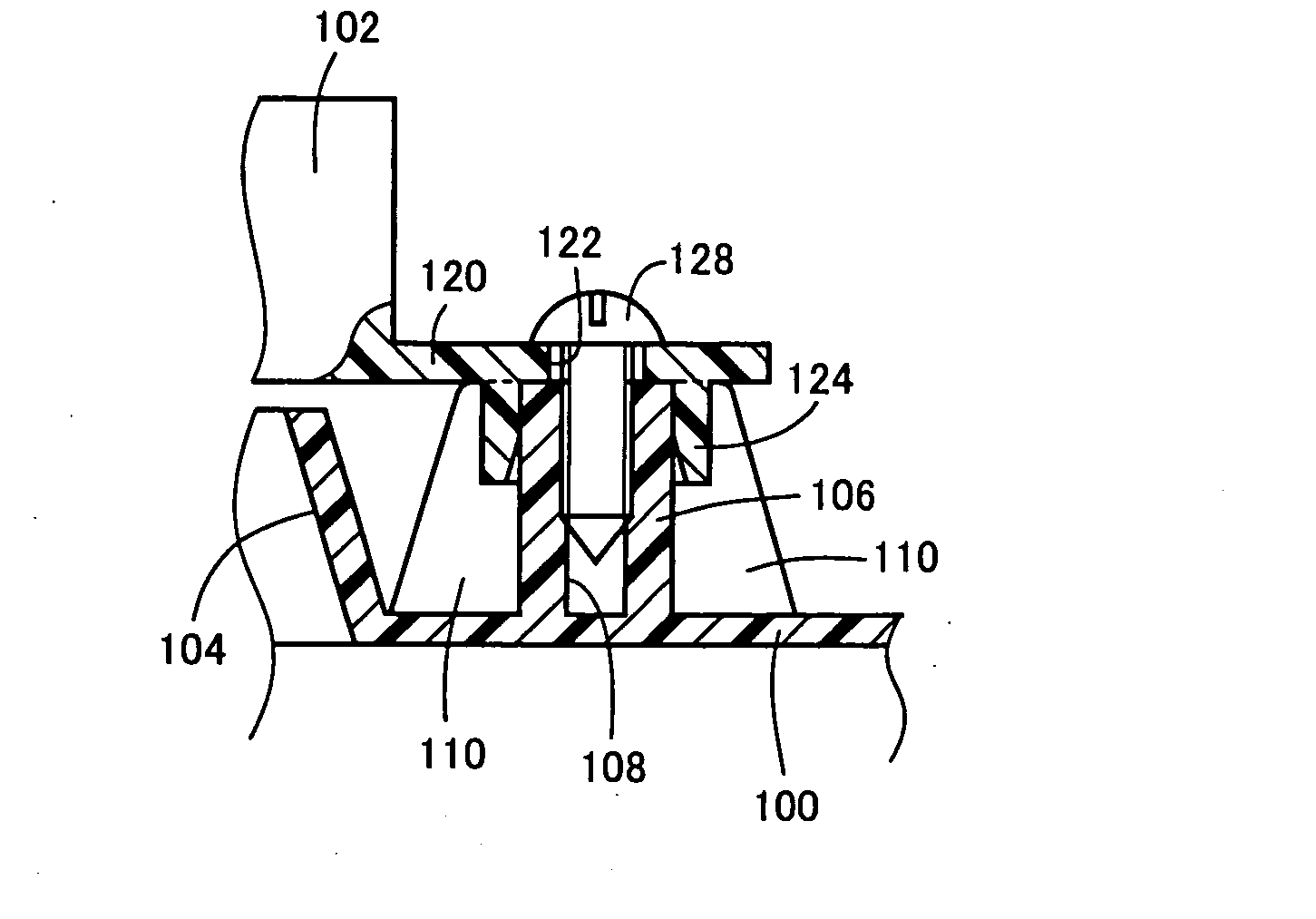
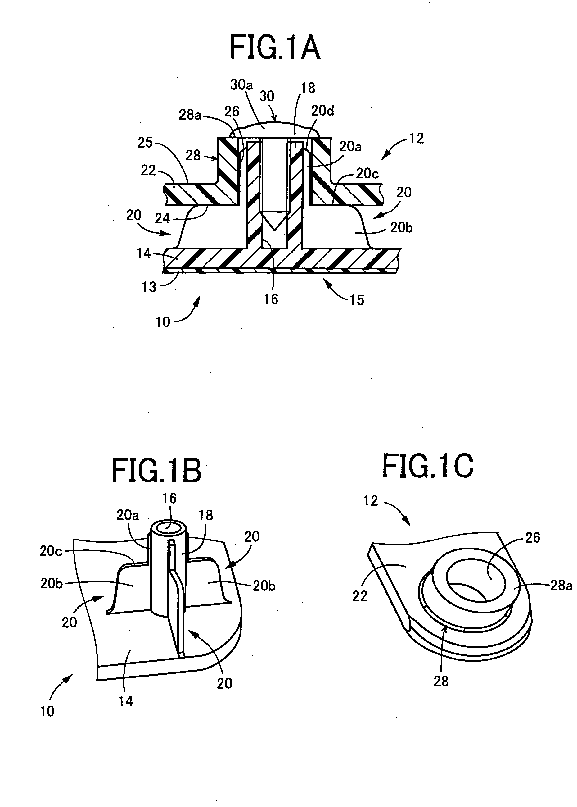
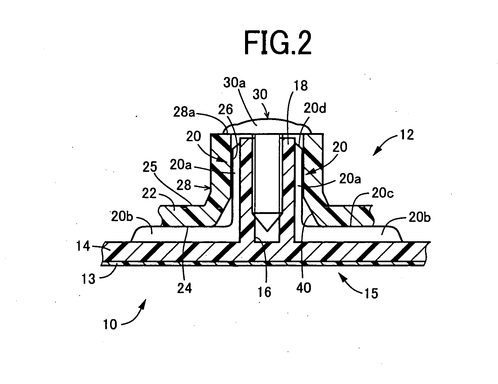
[0026]The first member and the second member are sufficiently fixed integrally by the mounting screw with positioned relative to each other. The position of the second member relative to the first member may be adjusted by fitting the positioning hole to the boss, or the position of the first member relative to the second member may be adjusted by fitting the boss into the positioning hole.

[0027]The first member and the second member have at portions or parts to be integrally fixed by the mounting screw, for example, flat plate portions which become parallel to each other in the mounted state. The boss and the tubular portion are disposed perpendicular to the flat plate portions. However, various another modes can be employed additionally. For example, one of the flat plate portions may be mounted in an inclined posture to the other flat plate portion. The boss and the tubular portion may be disposed on and fixed integrally to a deformed portion, such as bent shaped portion, wave-sh...


PUM


Abstract

A mounting part (second member) 12 has a positioning hole 26 to be fitted to an outer peripheral side of a boss 18 disposed on a vehicle interior part (first member) 10, to be positioned thereto. A facing surface 24 of the mounting part 12 is formed into a flat surface. By a slidable-contact of the flat facing surface 24 with a tip end of the boss 18 for a positional alignment, the positioning hole 26 can be fitted readily to the boss 18. A tubular portion 28 is disposed on a surface at a side opposite to the facing surface 24 to be fitted to the boss 18 substantially over its entire length thereof. Such fitting maintains the aligned state, so that a fastening work during fixing of the mounting part 12 by screwing a mounting screw 30 into a cylindrical hole 16 of the boss 18 is facilitated.

Description

[0001]The present application is based on Japanese Patent Application No. 2007-165651, and content thereof is incorporated herein.BACKGROUND OF THE INVENTION[0002]1. Field of the Invention[0003]The present invention relates to a member mounting structure and particularly relates to an improvement of a mounting structure, which with positioning a second member by a boss disposed on a first member, fixes a second member to the first member integrally by a mounting screw.[0004]2. Description of the Prior Art[0005]A mounting structure is known which presses a second member against a first member and integrally fixes it thereto. That is, in a state where a predetermined second member is positioned relative to a first member having a tubular boss with a screw fastening hole at its center using the boss as a reference, a mounting screw is screwed into the screw fastening hole. Thus, the second member is pressed against the first member and is thereby fixed integrally thereto by a head of t...

Claims


Application Information

Patent Timeline
Patent Type & Authority Applications(United States)
IPC IPC(8): F16B7/04
CPCF16B5/025F16B5/0258F16B17/008Y10T403/1624Y10T403/75Y10T403/335
Inventor HIROSE, MASAMORIOKADA, FUMIHIKOHIROSE, NAOKI
Owner TOYODA IRON WORKS CO LTD
Why Eureka
Try Eureka