Press-driven tool actuation system

a tool actuation and press-driven technology, applied in the direction of braking systems, rotary clutches, fluid couplings, etc., can solve the problems of large device weight, large component weight, and inability to meet the requirements of precise component alignment, etc., to achieve high stripping force, low profile, and high resistance to side thrust

Active Publication Date: 2009-01-01
DADCO INC
View PDF8 Cites 2 Cited by
  • Summary
  • Abstract
  • Description
  • Claims
  • Application Information

AI Technical Summary

Benefits of technology

[0006]At least some of the objects, features and advantages that may be achieved by at least certain embodiments of the invention include providing a hydraulically-operated press-driven tool actuation system that provides a relatively low profile and compact length of a hydraulically-driven tool actuator; may be used in any orientation on a press; provides high tooling forces per unit area of die used; enables a relatively high stripping force; offers high resistance to side thrust and torsional tooling forces; is operable under relatively high fluid pressure; allows for visual oil level monitoring; does not require a nitrogen gas accumulator or nitrogen gas pump rod return; and is of relatively simple design, economical manufacture and assembly, rugged, durable, reliable, and in service has a long useful life.

Problems solved by technology

But such devices are bulky, and require highly precise component alignment.
Although such devices are simpler and more flexible than the mechanical cams, they can be too bulky for certain small space applications.

Method used


Image

  • Press-driven tool actuation system
  • Press-driven tool actuation system
  • Press-driven tool actuation system

Examples


Embodiment Construction

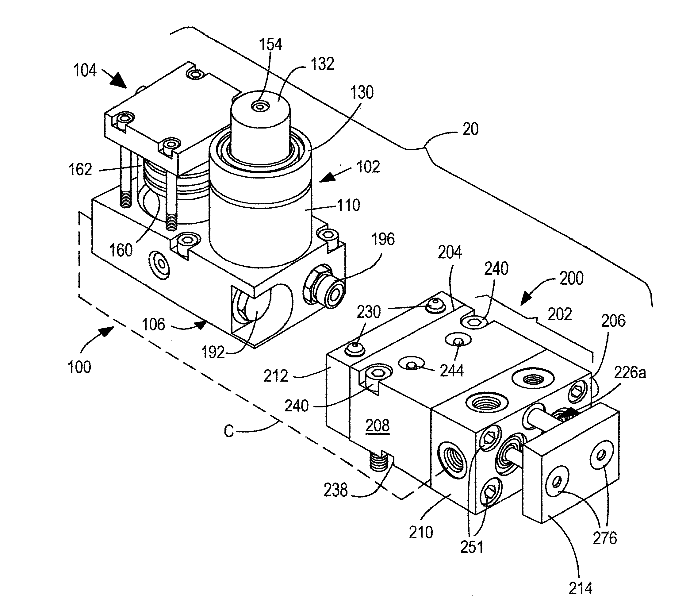
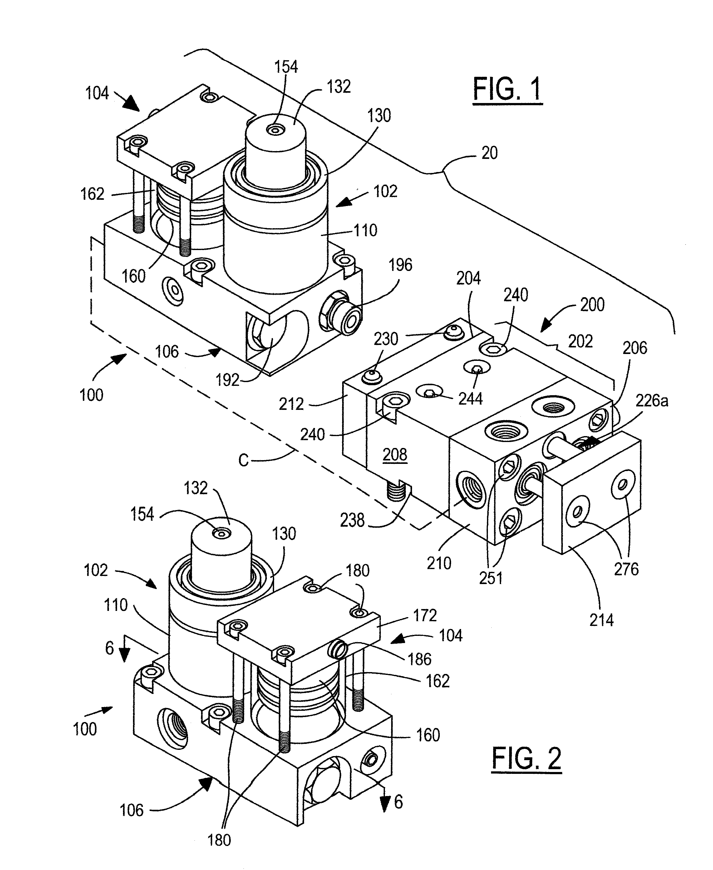
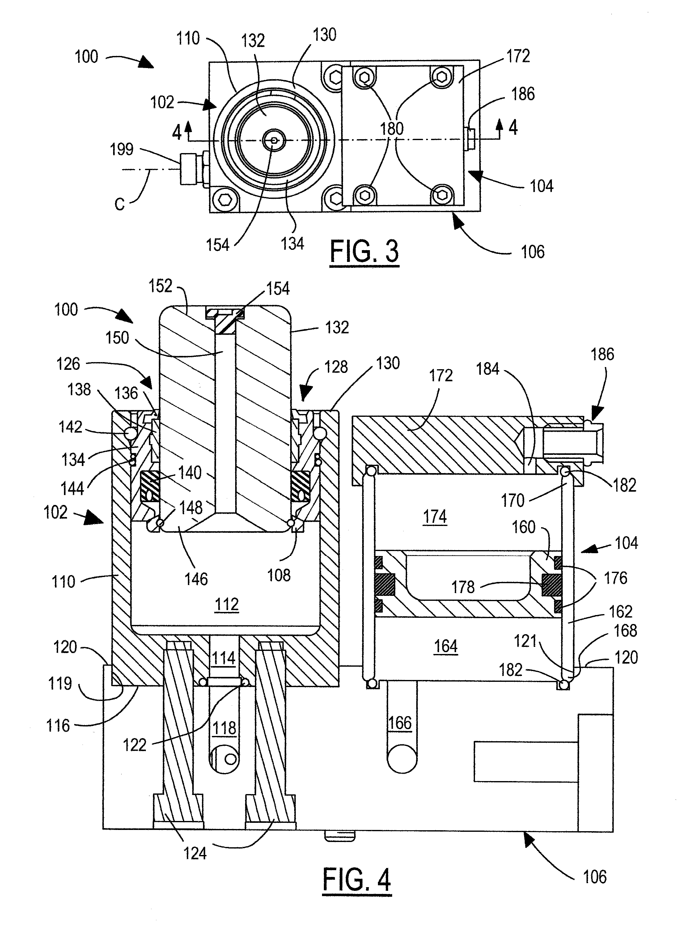
[0033]Referring in more detail to the drawings, FIG. 1 illustrates a hydraulically-operated press-driven tool actuation system 20 for actuating one or more press tools (not shown). The press tools could include any suitable forming tools such as punches, shears, drawing or bending tools, or the like. The system 20 is preferably adapted for use in a sheet metal forming press (not shown), which may include a bed carrying a lower platen and a ram carrying an upper platen, and upper and lower dies carried respectively by the upper and lower platens. A sheet metal blank (not shown) can be placed between the platens, wherein the upper die advances along a closing direction toward the lower die to form various features in the sheet metal blank.

[0034]In general, the system 20 includes a tool actuator 200 for actuating a press tool to form features on the sheet metal blank, a press-driven hydraulic power device 100 for converting mechanical motion from the press into hydraulic fluid pressure...


PUM

PropertyMeasurementUnit
hydraulic pressureaaaaaaaaaa
inner diameteraaaaaaaaaa
transparentaaaaaaaaaa

Abstract

A hydraulically-operated press-driven tool actuation system includes a press-driven hydraulic power device and / or a hydraulically-powered tool actuator. In the tool actuator, at least two pistons are carried by a housing, and at least one return device is carried by the housing laterally inboard of the pistons. In the power device, a pump includes a piston disposed in a pump cylinder for pressurizing hydraulic fluid therein. An accumulator is in fluid communication with the pump cylinder, and includes a piston disposed in an accumulator cylinder that houses hydraulic fluid on one side of the piston. A body supports the pump and accumulator thereon and is in fluid communication between the pump and accumulator cylinders. The body includes a pressure relief valve downstream of the pump cylinder and upstream of the accumulator cylinder, and a check valve downstream of the accumulator cylinder and upstream of the pump cylinder.

Description

FIELD OF THE INVENTION[0001]The present invention relates generally to tool actuation systems and, more particularly, press-driven tool actuation systems.BACKGROUND OF THE INVENTION[0002]In manufacturing parts from sheet metal, a metal forming press forms a flat sheet of metal positioned between upper and lower platens. The upper platen carries an upper die and is closed toward a lower die carried by the lower platen wherein certain portions of the sheet are cut, bent, drawn, or pierced by different features of the dies. Sometimes, separate press-mounted devices form other portions of the sheet along a direction different from the closing direction of the press. Accordingly, press-driven tool actuators convert press closing motion into transverse tool motion, and typically include mechanically or hydraulically actuated “cams.”[0003]Mechanically actuated cams include an adapter body mounted to the upper platen or a die, a slider mounted on the adapter body to drive a tool affixed the...

Claims


Application Information

Patent Timeline
Patent Type & Authority Applications(United States)
IPC IPC(8): B30B1/00F15B1/24F15B7/00
CPCB30B1/32F15B15/1476F15B15/1404B21D28/002B21D28/32
Inventor COTTER, JONATHAN P.KLUCK, JEREMY M.VANDINE, JASON L.
Owner DADCO INC
Why Eureka
Try Eureka