Apparatus and methods for refurbishing ice surfaces

a technology of ice surface and apparatus, applied in the direction of skiing, construction, roads, etc., can solve the problems of affecting the composition, affecting the quality of ice surface, so as to achieve the effect of quick creation of new ice surfa

Inactive Publication Date: 2009-01-01
SCI STOCK COMPOSITE
View PDF9 Cites 13 Cited by
  • Summary
  • Abstract
  • Description
  • Claims
  • Application Information

AI Technical Summary

Benefits of technology

[0008]The apparatus and methods of this patent disclosure will generally serve to eliminate, or at least greatly reduce, the need for a Zamboni-type machine in order to refurbish an ice surface. This implies that the considerable costs associated with purchasing, operating, maintaining, insuring and storing machines of this kind can be eliminated or greatly reduced. Moreover, for reasons hereinafter more fully explained, the quality of the new ice surfaces created through use of Applicant's apparatus and methods will be inherently higher than those that can be achieved by Zamboni-type machines. Another added advantage associated with the practice of this invention is the fact that the time needed for a given ice resurfacing operation can be greatly reduced. For example, the ten to fifteen minutes needed for a Zamboni resurfacing of an ice hockey rink can be shortened to one to two minutes—or even less—through use of the present invention. Moreover, Applicant's shortened job time requirements—in conjunction with the higher quality ice surfaces that can be achieved—present an opportunity to print certain visual information (such as advertisements) on the newly resurfaced ice. Opportunities to place such printing under an ice surface also arise through application of this invention.
[0028]Upon reaching the opposing end of the rink, the ice shavings collected in the ice scoop system are disposed of (e.g., by dumping, heating, augering, paddling, etc.). Thereafter, the ice scoop is pulled back across the ice surface to its home position beyond the left end of the ice surface. The ice blade system can follow the ice scoop back to its home position (also located beyond the left arcuate end zone). In the alternative, the ice scoop system—still filled with ice shavings—can be powered back to the left end zone where the ice shavings are disposed of. This implies that much of, or even all of, the apparatus and equipment located in the right end zone apparatus, right end zone trench and / or right end structure can be eliminated.
[0033]The above noted ability of the apparatus and methods of this patent disclosure to quickly create new ice surfaces also creates opportunities to place written information under the top surface of newly formed ice—rather than upon the top surface of such ice. By way of example only, the ice surface may be shaved to some desired relatively deep depth (e.g., from about ¼ to ½ inch) by a series of ice shaving passes using relatively shallow ice shaving depths (e.g., from about 1 / 32 to about ¼ inch). When the desired depth is attained, an image (or other information) is then printed upon the ice surface at the desired depth. Thereafter, a first water dispensing pass is made over the ice surface having the printed image, information, etc. The layer of water laid down in this water dispensing pass will quickly freeze (e.g., in about 30 seconds) into a first layer of print-covering ice. After that, a second water dispensing pass will be made over the first layer of print covering ice to create a second layer of print covering ice. This second layer will likewise very quickly freeze. This process can be repeated over and over again until the cumulative layer of print covering ice has attained some desired thickness (e.g., from ¼ to ½ inch) and thereby protecting the printed image, information, etc. from ice skate gouges in the ice surface.

Problems solved by technology

Not the least of these is the fact that many of these ice surfaces are routinely gouged and pitted by ice skate blades.
This is done because such minerals and chemicals tend to detrimentally alter the composition of a new ice layer made from impure waters (e.g., making the resulting new ice relatively more brittle, or more soft, or sometimes even giving it pungent odors).
The presence of such impurities also tends to make the resulting new ice layer undesirably “cloudy” or opaque in its visual appearance.
Nonetheless, the ice surfaces around the edges of ice rinks have a tendency to build up because a Zamboni blade does not normally fully extend beyond the sled's outer edge.
Ice edgers have not, however, always effectively dealt with the fact that the ice immediately contiguous to the sides of dasher boards tends to build up in ever enlarging bodies of ice having fillet-like cross-sectional configurations.
Venerable as they are however, Zamboni-type ice resurfacing machines do have certain inherent limitations and / or drawbacks.
Thus they are always confronted with gaining wheel traction on these icy surfaces.
Nonetheless, certain problems inherently arise from the fact that a great deal of force is needed to scrape even a thin layer of ice (e.g., 1 / 32 inch) from the top of an ice surface over a typical 80 inch width of a Zamboni ice shaving blade.
However, as more and more weight is placed over the blade in order to help it achieve and maintain a desired uniform ice shaving depth, the Zamboni's tires will have a progressively more difficult time gaining traction on the ice surface.
Indeed, these opposing, weight over blade vs. wheel traction considerations have, in effect, limited the width of the ice cut that can be made by a given Zamboni blade.

Method used


Image

  • Apparatus and methods for refurbishing ice surfaces
  • Apparatus and methods for refurbishing ice surfaces
  • Apparatus and methods for refurbishing ice surfaces

Examples


Embodiment Construction

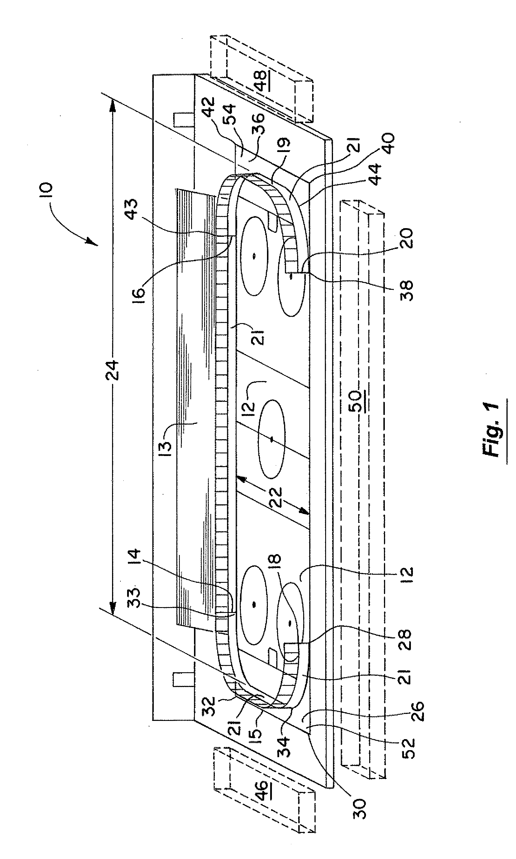
[0054]FIG. 1 is a perspective view of an ice sport facility 10 having an ice surface 12 and spectator seating 13. The ice surface 12 is depicted as having a configuration and markings appropriate to the game of ice hockey. For example, its center region is rectangular in configuration and each end of the rectangular center region is respectively contiguous to an arcuate end zone region. Most of the perimeter of this ice hockey playing surface is shown surrounded by a dasher board system that normally has a height of approximately 40 inches (about 1 meter). Such dasher board systems are often referred to colloquially as “the boards.” The parallel, linear portions (e.g., 14-16 and 18-20) of such ice hockey rinks are often referred to as “the side boards.” Similarly, the arcuate end zone portions of such a dasher board system are sometimes referred to as the “end zone boards.” The arcuate, left end zone dasher board portion of the boards shown in FIG. 1 is designated by item numbers 14...


PUM


Abstract

An apparatus and method for resurfacing ice surfaces such as ice hockey playing surfaces wherein an ice shaving blade system and an ice scooping system operate over the entire width of (or the entire length of) said playing surface.

Description

BACKGROUND OF THE INVENTION[0001]This invention is generally concerned with apparatus and methods for resurfacing those ice surfaces upon which certain ice sports and / or recreational activities take place e.g., ice hockey games, ice shows, public recreational skating, speed skating contests, ice curling, etc. The need to periodically refurbish / resurface / refinish such ice surfaces arises for various reasons. Not the least of these is the fact that many of these ice surfaces are routinely gouged and pitted by ice skate blades. The cutting action of ice skate blades also tends to create small piles of “snow” that sometimes interfere with certain high skill activities needed for some ice sports e.g., imparting straight travel paths to ice hockey puck shots.[0002]Various machines have been developed over the years to carry out ice refurbishing operations. These machines usually take the form of truck-like vehicles that clean, smooth and resurface an ice rink's gouged and pitted ice surfa...

Claims


Application Information

Patent Timeline
Patent Type & Authority Applications(United States)
IPC IPC(8): A63C19/10
CPCE01H4/023
Inventor WALKER, JOHN A.
Owner SCI STOCK COMPOSITE
Why Eureka
Try Eureka