Airbag for vehicle tires

a technology for airbags and tires, applied in envelopes/bags making machinery, paper/cardboard containers, other domestic objects, etc., can solve the problems of airbags being prone to failure and losing pressure, and achieve the effect of stabilizing the auto and ensuring the driving comfor

Inactive Publication Date: 2009-01-01
FAN
View PDF1 Cites 6 Cited by
  • Summary
  • Abstract
  • Description
  • Claims
  • Application Information

AI Technical Summary

Benefits of technology

[0007]Therefore, it is one objective of the present invention to provide an airbag device for a vehicle tire capable of stabilizing the auto timely when the tire is exploding or being punctured suddenly, keeping a normal running performance, and meanwhile, ensuring the driving comfort.

Problems solved by technology

However, air-filled tires are prone to failure and loss of pressure at which time flat tires must be replaced immediately.
Especially, when a tire has exploded or is punctured suddenly at a high running speed, the vehicle may lose balance potentially causing a serious accident.

Method used


Image

  • Airbag for vehicle tires
  • Airbag for vehicle tires
  • Airbag for vehicle tires

Examples


example 1

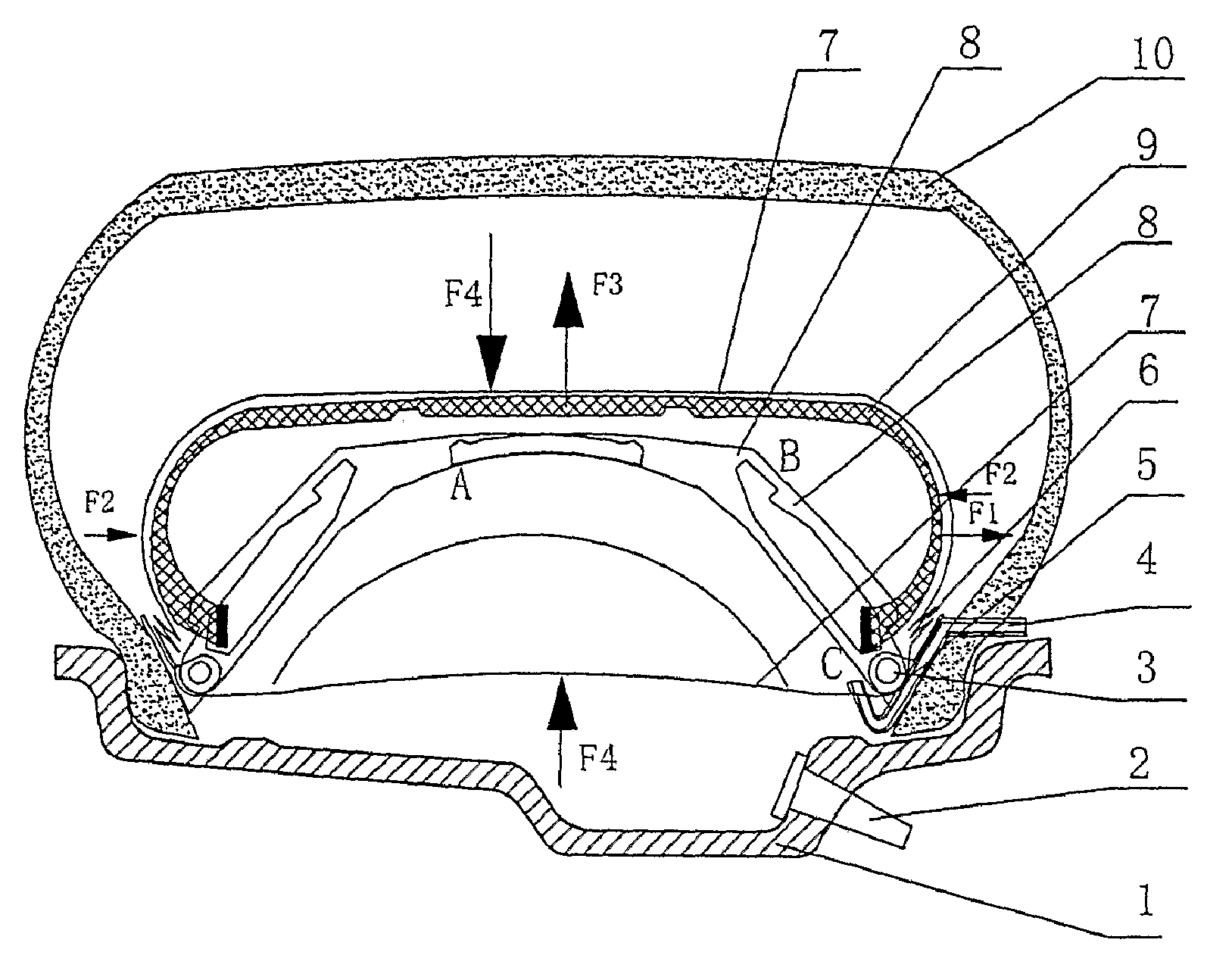
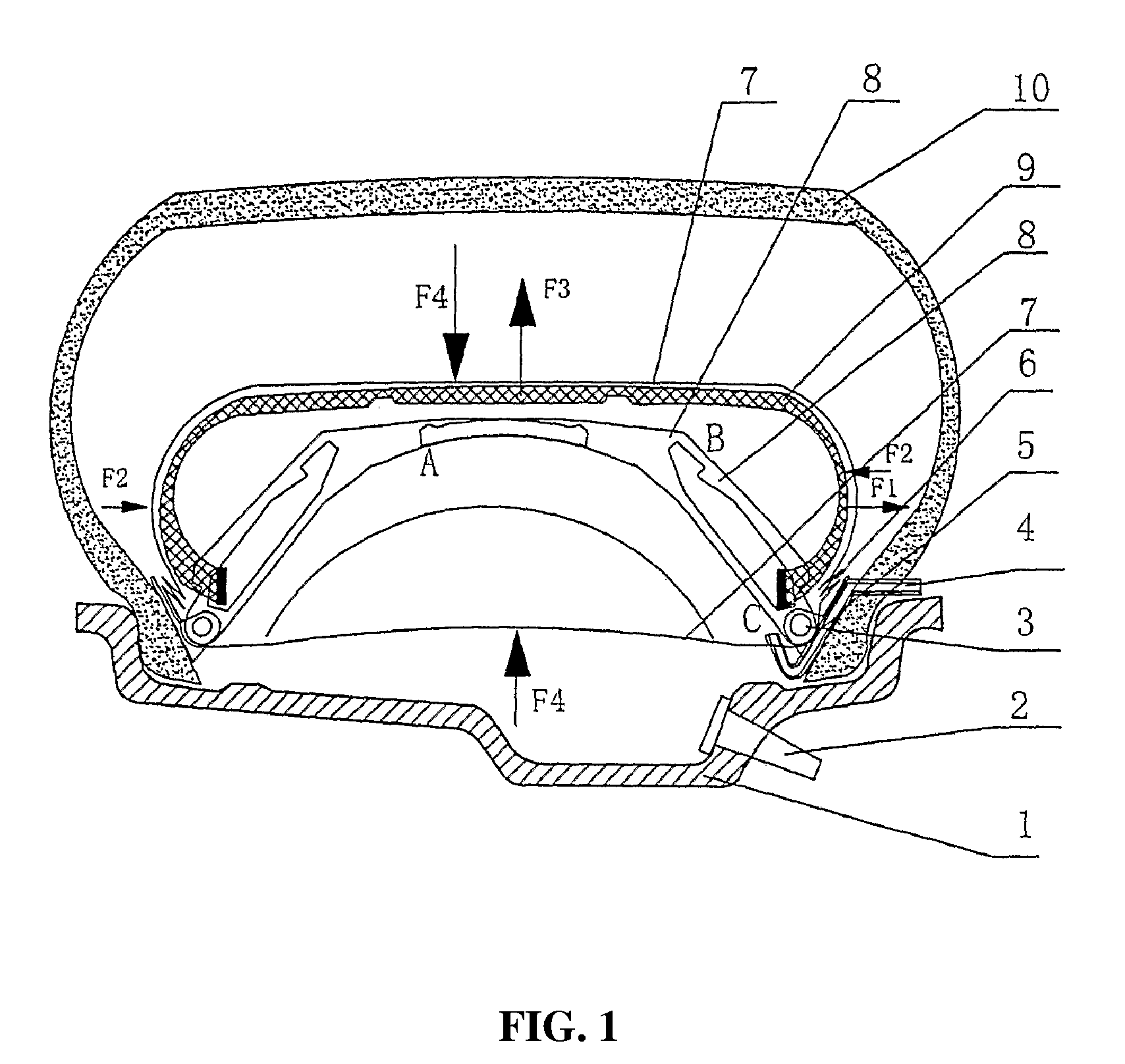
[0033]As shown in FIGS. 1-2, an airbag device for a vehicle tire comprises a resilient outer ring, an inner ring, and an airbag. The resilient outer ring is formed through the connection of an outer supporting member 9 and is compressible. The inner ring comprises an inner supporting member 8 and is fixed on the wheel hub 1 by a tightening ring 3. The tightening ring 3 is made of steel wire or carbon fiber. The outer ring of the airbag device is a compressible resilient body connected by a plurality of outer supporting members 9. In the event that a tire explodes, as shown in FIG. 2, the bottom end of the outer supporting member 9 slides on the section labeled BC of the inner supporting member 8. The tangential direction of the circumference of the outer ring has a certain degree of resilience. The two resilient sides of the outer supporting member 9 have enough resilient force F2 to ensure that the inner supporting member 8 bounces instantly and is then locked at point B.

[0034]As s...

example 2

[0038]Differentiated from Example 1, the inner ring and the resilient outer ring are designed as two separate parts. The size of the resilient outer ring can be changed accordingly since the resilient outer ring is sliding on the inner ring. As shown in FIGS. 3-4, the inner ring and resilient outer ring are formed as one piece. The resilient deformation of the inner ring 8 is utilized to adjust the size of the resilient outer ring. As shown in FIG. 4, when the tire air pressure is normal, the air pressure compresses the inner ring bent deformed inwardly, and at the same time, the resilient outer ring 9 is compressed inwardly until it is locked by clip 16. As shown in FIG. 4, when the air pressure of the tire is lost, the clip 16 is released and deformed under the function of tire tread pressure, and the airbag device is then unfolding.

examples 3

[0039]As shown in FIGS. 5-6, at least one inner supporting member 11 and at least one lateral supporting member 12 serve to form a fixed supporting member. The bottom end of the lateral supporting member 12 is connected with a push rod 15, and the connection point (point K) therebetween serves to lock the bottom end of, and thus to fix, the inner supporting member 11. When disassembling the tire, pushing and compressing the outer edge of the tire to release the lateral supporting member 12 from point K of the inner supporting member 11 via the push rod 15. The inner supporting member is then capable of being bent inwardly to push the tire edge to the deep slot of the wheel hub so that the tire can be disassembled and repaired.

[0040]As shown in FIG. 5, the airbag 7 can be located between the inner supporting member 11 and the outer supporting member 9. Under normal tire pressure, the tire pressure is utilized to compress the outer supporting member 9 to point B and then is fixedly-lo...


PUM


Abstract

An airbag device for a vehicle tire capable of stabilizing the vehicle timely when the tire is exploding or being punctured suddenly to avoid potential accidents and to ensure driving comfort. The airbag device comprises a resilient outer ring installed between the tire and the wheel hub, and an inner ring serving to support the resilient outer ring. The resilient outer ring and the inner ring are compressed between the tire and the wheel hub under normal tire air pressure, and a space serving to increase driving comfortability and keep the outer ring from contacting the inner surface of the tire tread is designed between the resilient outer ring and the inner surface of the tire tread. When the tire is exploding or the air pressure of the tire is lost, the resilient outer ring is capable of bouncing instantly to support the weight of the vehicle.

Description

BACKGROUND OF THE INVENTION[0001]1. Field of the Invention[0002]The invention relates to a vehicle tire safety device, and more particularly, to an airbag device for a vehicle tire, which allows the tire to continue operating safely after failure, e.g., explosion or puncture, without loss of stability and for an extended period of time without the need for tire replacement.[0003]2. Description of the Related Art[0004]Conventional vehicle tires are air-filled (pneumatic) and offer the advantages of good comfort and low road resistance. However, air-filled tires are prone to failure and loss of pressure at which time flat tires must be replaced immediately. Especially, when a tire has exploded or is punctured suddenly at a high running speed, the vehicle may lose balance potentially causing a serious accident. Many solutions to this problem have been proposed.[0005]The solutions are mainly classified into two types. The first type is to install a supporting rim inside of the tire. See...

Claims


Application Information

Patent Timeline
Patent Type & Authority Applications(United States)
IPC IPC(8): B60C17/04
CPCB60C17/02Y10T152/10522Y10T428/13B60C17/01
Inventor FAN, LIANG
Owner FAN
Why Eureka
Try Eureka