
Thermal management in imaging reader

a technology of thermal management and imaging reader, which is applied in the direction of sensing record carrier, dynamo-electric converter control, instruments, etc., can solve the problems of significant heat generation, degrade the performance of the imager itself, and reduce the operating lifetime of the leds and other reader components, so as to improve the performance of the reader, dissipate the excess heat, and improve the effect of reading performan

Active Publication Date: 2009-01-01
SYMBOL TECH LLC
View PDF6 Cites 7 Cited by
  • Summary
  • Abstract
  • Description
  • Claims
  • Application Information

AI Technical Summary

Benefits of technology

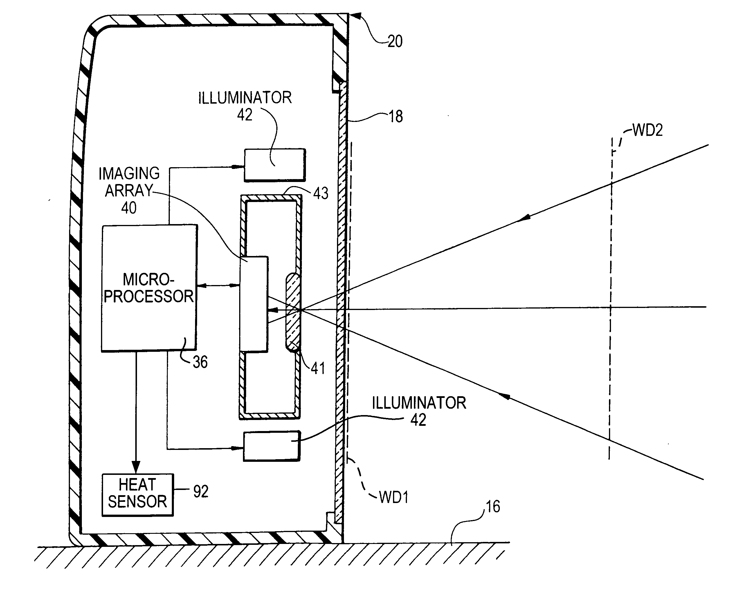
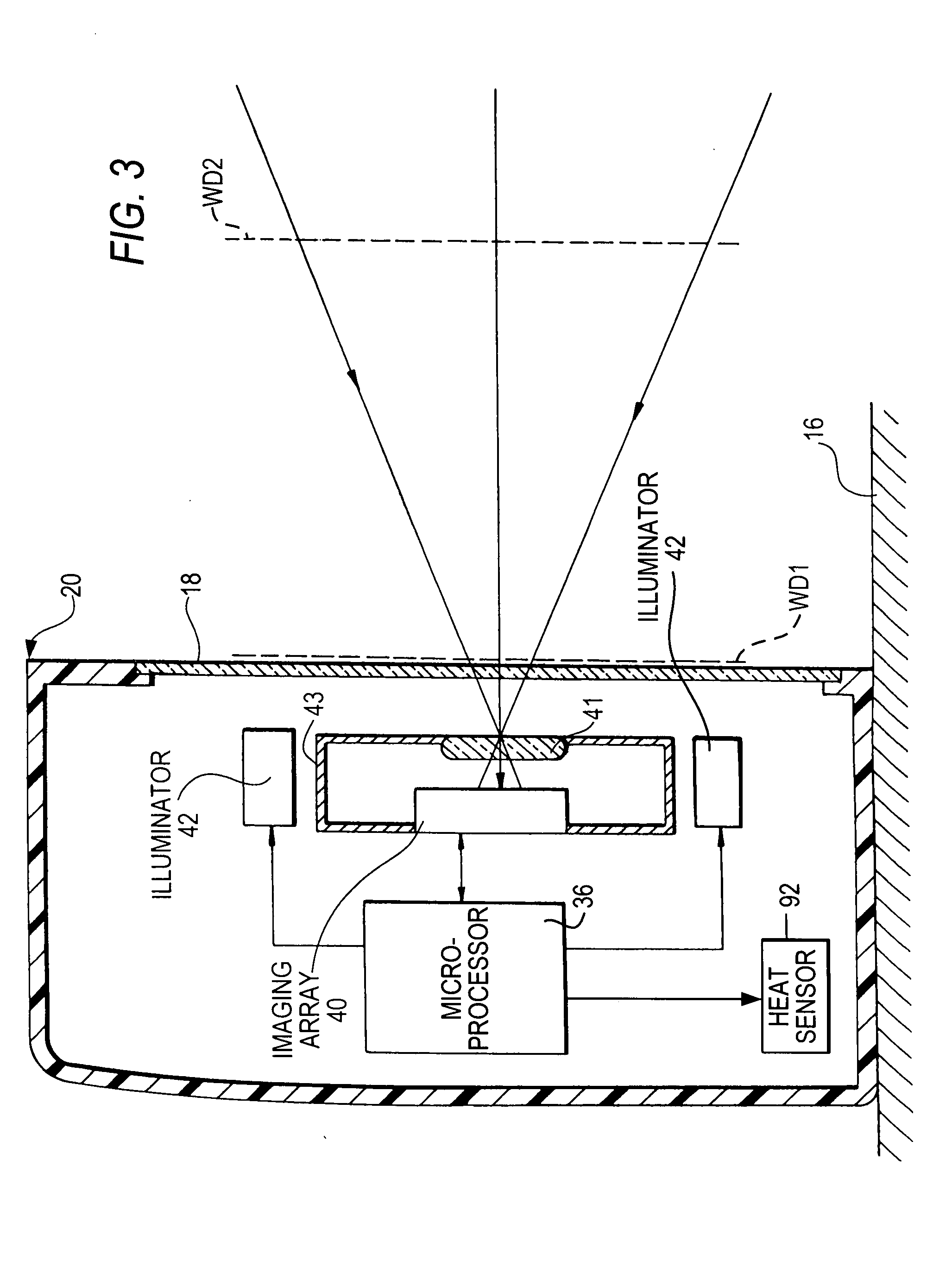
[0013]As discussed above, the reading performance of the imaging reader is highly dependent on the level of the illumination light that is directed to the symbol. The higher the level of the illumination light, the better is the reading performance. Hence, high-powered light source(s) are electrically driven at relatively high electrical drive currents, thereby projecting high intensity illumination light onto the symbol. This, however, concomitantly undesirably generates significant excess heat that can degrade and shorten the working lifetime of components of the reader, especially the imager, the light source(s) and the controller.
[0014]In accordance with one aspect of the invention, various thermal management procedures are employed to dissipate the excess heat to improve reader performance. For example, each illumination LED is surface-mounted on one of a pair of opposite surfaces of a printed circuit board. Thermally conductive, metallized lands or pads, preferably of copper, are plated on the opposite surfaces of the board. A hole extends through the opposite surfaces of the board and is internally plated and lined with a thermally conductive, metallized layer, preferably of copper, in thermal communication with the lands on the opposite surfaces of the board. The LED is in thermal communication, preferably by soldering, with one of the lands to conduct the excess heat away from the LED from one of the lands on one surface via the plated hole to the lands on the opposite surface. This thermal management procedure is especially recommended when the board is small in area such that the lands on one surface, i.e., the front surface, of the board are insufficient in area to radiate the excess heat to the environment. By also using the land on the opposite rear surface to dissipate the excess heat, the total area for radiating the excess heat to the environment is increased, and the heat-sinking capability is enhanced.
[0020]One possible thermal management procedure could be to inhibit activation of the LEDs and other components of the engine entirely until such time as the temperature returns to an acceptable threshold level. Another possibility is to reduce the time that the LEDs are permitted to be turned on for each exposure of the imager. Other possibilities are to reduce the current to the LEDs during an exposure, to reduce the number of LEDs that are actuated, or to reduce the frequency with which the LEDs can be activated. An example of reducing LED activation frequency would be to reduce the number of images that the imager can capture each second, thereby eliminating the need to activate the LEDs as frequently. For example, some area imagers are capable of capturing images at up to 60 frames per second. This high frame rate can help the reader feel more responsive to a user, but in the case of an impending overheating condition, the frame rate might be reduced to 50, 40, or 30 frames per second, etc., as necessary, to achieve an acceptable temperature. This would permit the LEDs to be turned off during the time when the additional frames would otherwise be occurring. Users might notice a small loss of responsiveness when the number of frames is reduced, but this is preferable to failure of the reader.
[0024]In accordance with another aspect of the invention, the method of electro-optically reading indicia, comprising the steps of capturing return light from the indicia during reading by using a solid-state imager including an array of image sensors; generating and directing high intensity illumination light from a light source to the indicia with concomitant generation of excess heat; and dissipating the excess heat to improve reader performance.
[0025]In accordance with yet another aspect of the invention, an imaging module for use in electro-optically reading indicia, comprises a chassis; a solid-state imager supported by the chassis, including an array of image sensors for capturing return light from the indicia during reading; a light source supported by the chassis, for generating and directing high intensity illumination light to the indicia with concomitant generation of excess heat; and means for dissipating the excess heat to improve reading performance.
[0026]Hence, by removing the excess heat, the operating lifetimes of the imager, the LEDs, the controller and other reader components are extended, and the performance of the reader is enhanced.

Problems solved by technology

If higher levels of the illumination light are to be projected from the imaging module for better reading performance, it will be necessary to drive the illumination LEDs that are mounted on the module at relatively high electrical drive currents, thereby concomitantly causing significant heat generation.
Although the known imaging readers are generally satisfactory for their intended purpose, this heat generation can cause significant problems, especially when the module is operating in a hot environment, and / or when installed in a housing that does not allow for heat dissipation.
Excessive heat can reduce the operating lifetimes of the LEDs and other reader components, and can also degrade the performance of the imager itself.
Some modules use a laser or LED aiming pattern generator to project an aiming pattern or mark on the symbol, which can also generate undesirable, and be damaged by, excessive heat, as well as degrading other components within the reader.

Method used


Image

  • Thermal management in imaging reader
  • Thermal management in imaging reader
  • Thermal management in imaging reader

Examples


Embodiment Construction

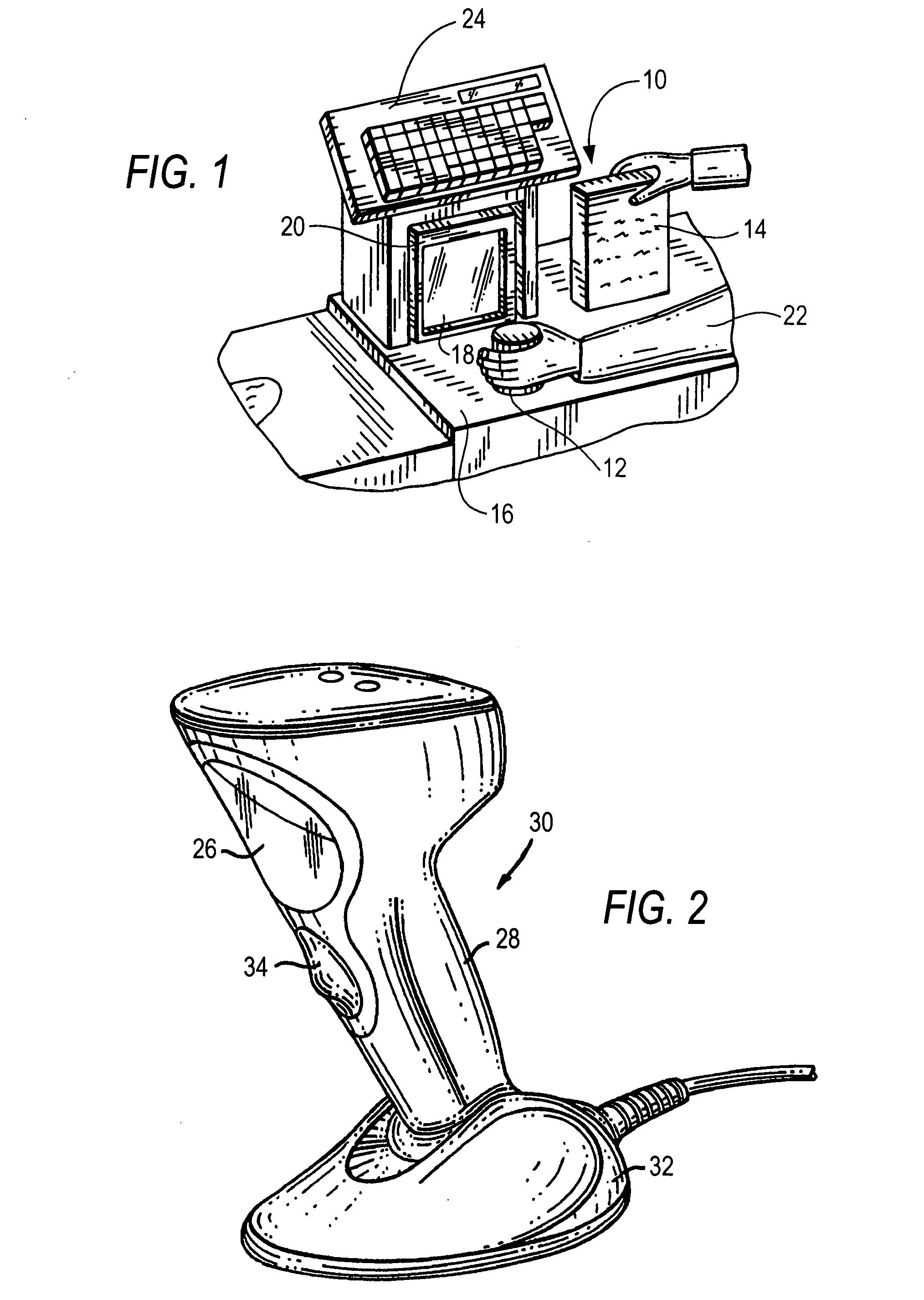
[0036]Reference numeral 10 in FIG. 1 generally identifies a workstation for processing transactions and specifically a checkout counter at a retail site at which products, such as a can 12 or a box 14, each bearing a target symbol, are processed for purchase. The counter includes a countertop 16 across which the products are slid at a swipe speed past a generally vertical window (i.e., presentation area) 18 of a box-shaped, portable, vertical slot, imaging reader 20 mounted on the countertop 16. A checkout clerk or operator 22 is located at one side of the countertop, and the reader 20 is located at the opposite side. A cash / credit register 24 is located within easy reach of the operator. In the frequent event that large, heavy, or bulky products, that cannot easily be brought to the reader 20, have target symbols that are required to be read, then the operator 22 may also manually grasp the portable reader 20 and lift it off, and remove it from, the countertop 16 for reading the ta...


PUM


Abstract

A reader for electro-optically reading indicia, includes a solid-state imager including an array of image sensors for capturing return light from the indicia during reading, and a light source for generating and directing high intensity illumination light to the indicia with concomitant generation of excess heat. Thermal management procedures for dissipating the excess heat are performed to improve reader performance.

Description

DESCRIPTION OF THE RELATED ART[0001]Flat bed laser readers, also known as horizontal slot scanners, have been used to electro-optically read one-dimensional bar code symbols, particularly of the Universal Product Code (UPC) type, at a point-of-transaction workstation in supermarkets, warehouse clubs, department stores, and other kinds of retailers for many years. As exemplified by U.S. Pat. No. 5,059,779; No. 5,124,539 and No. 5,200,599, a single, generally horizontal window is set flush with, and built into, a generally horizontal countertop of the workstation. Products to be purchased bear an identifying symbol and are typically slid or swiped across the generally horizontal window through which a multitude of scan lines in a scan pattern is projected in a generally upward direction. Each scan line is generated by sweeping a laser beam from a laser. When at least one of the scan lines sweeps over a symbol associated with a product, the symbol is processed and read, and the product...

Claims


Application Information

Patent Timeline
IPC IPC(8): G06K7/10
CPCG06K7/10544G06K7/10732G06K7/10584
Inventor BARKAN, EDWARDDRZYMALA, MARKCARLSON, BRADLEY
Owner SYMBOL TECH LLC
Learn More