Modular Near-Shore Wave-Powerd Energy Collection System

a technology of near-shore wave power and energy collection system, which is applied in the direction of sea energy generation, water power plants, electrical equipment, etc., can solve the problems of unpredictable energy amount, inconvenient installation and maintenance, and costly cabling systems, and achieves easy installation and maintenance.

Inactive Publication Date: 2009-01-01
WAVE POWER SOUTH
View PDF7 Cites 8 Cited by
  • Summary
  • Abstract
  • Description
  • Claims
  • Application Information

AI Technical Summary

Benefits of technology

[0010]It is an object of the present invention to provide a modular near-shore wave-powered energy colle...

Problems solved by technology

This creates two major problems.
The first is that the amount of energy is unpredictable and can vary from negligible amounts to storm related destructive...

Method used


Image

  • Modular Near-Shore Wave-Powerd Energy Collection System
  • Modular Near-Shore Wave-Powerd Energy Collection System
  • Modular Near-Shore Wave-Powerd Energy Collection System

Examples


Embodiment Construction

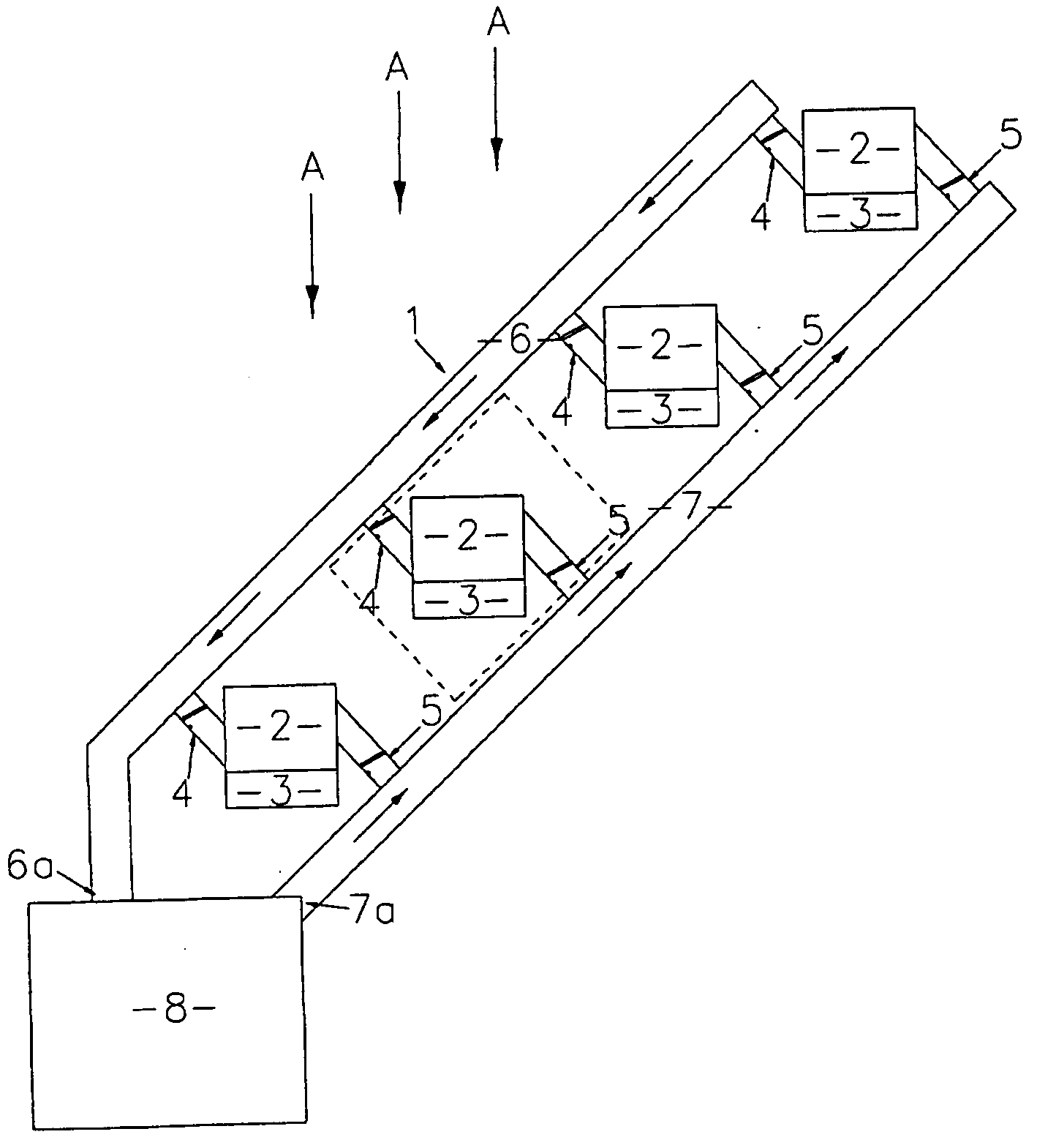
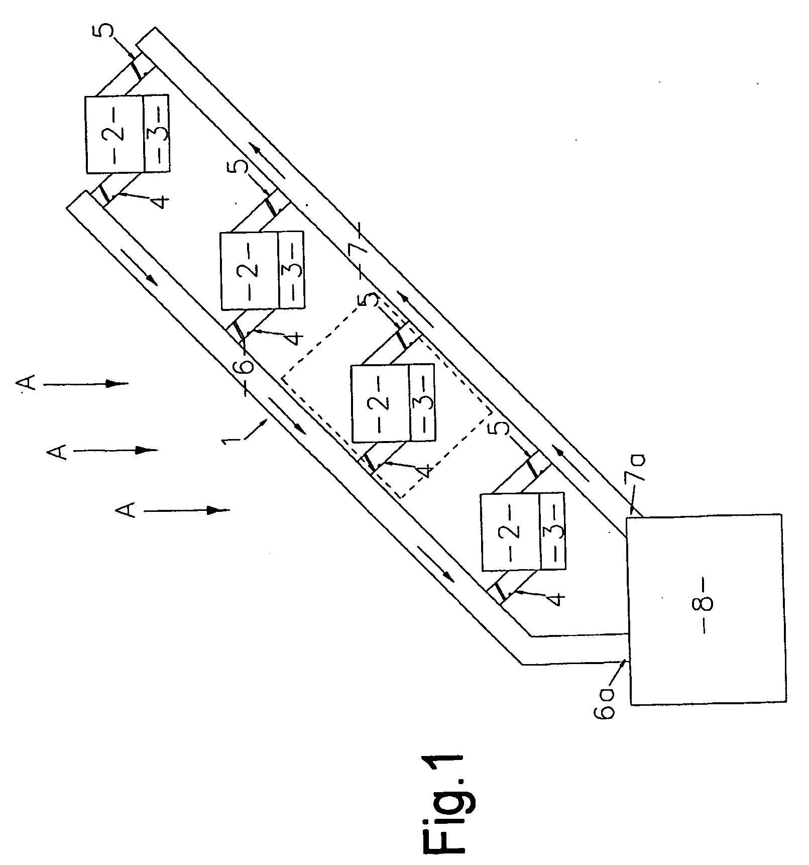
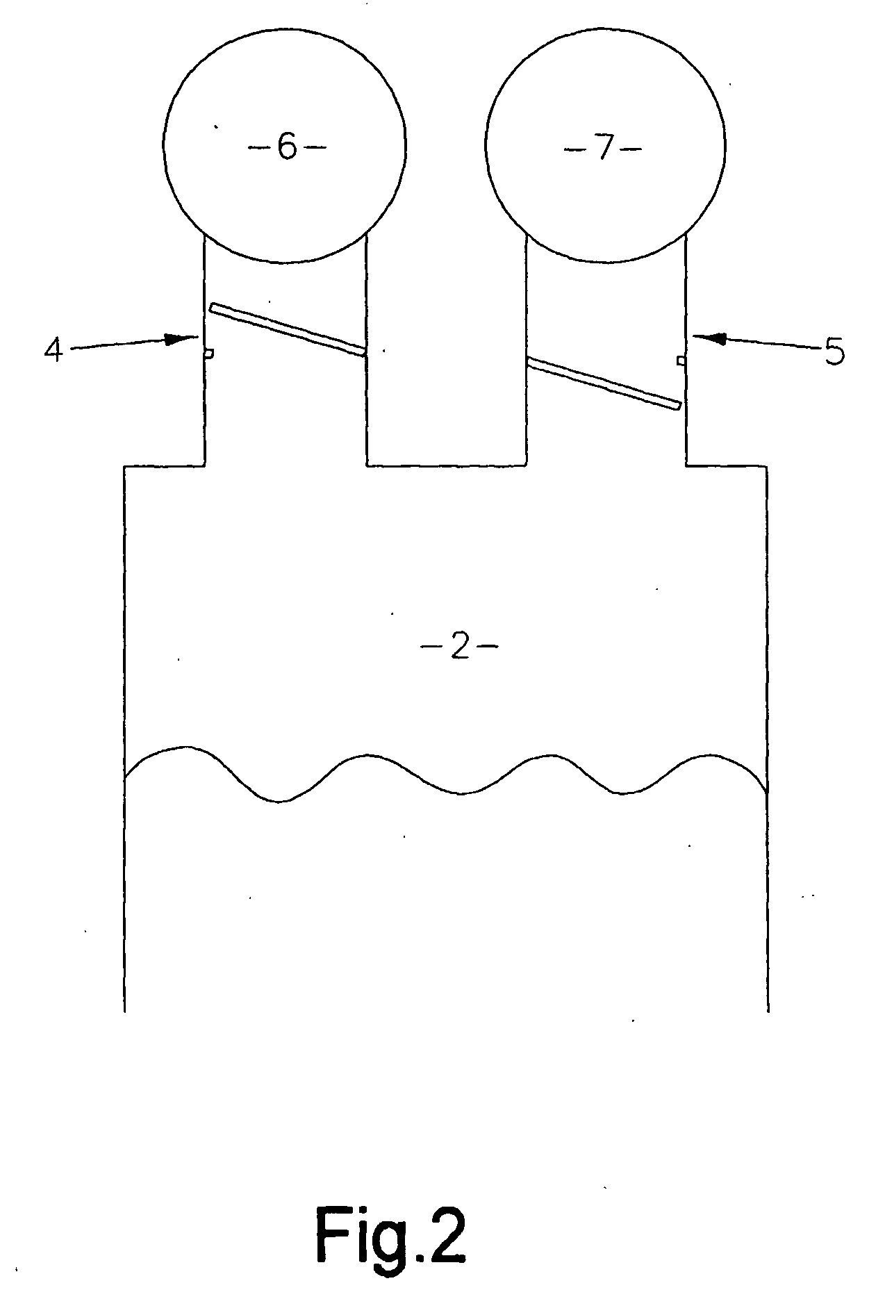
[0027]In a preferred embodiment each module of the modular near-shore wave-powered energy collection system consists of one OWC 2 and a flotation device 3. The OWC 2 is constructed of metal and has an oblong cross-section, with an open lower end. The OWC 2 is connected via valves 4 and 5 to common pressure manifold 6 and common vacuum manifold 7 respectively. Optionally drain tubes (not shown) may be provided above valve 4 to allow water to drain away.

[0028]As the water level rises and falls, pressure and suction are alternately created at the top of the OWC 2. When positive pressure is created, the valve 4 to common pressure manifold 6 opens, releasing the air into common pressure manifold 6. Conversely, when suction is created, the valve 4 to common pressure manifold 6 closes, and the valve 5 to common vacuum manifold 7 opens.

[0029]Multiple modules 1 are rigidly connected together so that a plurality of OWCs 2 are connected to common pressure manifold 6 and are also connected to c...


PUM


Abstract

A modular near-shore wave-powered energy collection system, which includes a plurality of connected modules, each module including at least one flotation device and at least one OWC, wherein each OWC is connected to a common pressure manifold and a common vacuum manifold and the common pressure manifold and the common vacuum manifold are connectable to a device.

Description

TECHNICAL FIELD[0001]The invention relates to the harnessing of wave energy for power generation and other applications.BACKGROUND[0002]The search for sustainable energy sources has prompted many studies into wave generation. One device commonly used in wave generation systems is an Oscillating Water Column (OWC). This is a hollow vessel, with one open end. When partially submerged in waves, with the open end in the water, the OWC contains a column of water and a region of air trapped at the top. The water level within the OWC alternately rises and falls with the waves. This acts as a piston and creates a corresponding pattern of alternating positive and negative pressure at the top of the OWC.[0003]This comprises a partly submerged structure which is open to the sea below the water surface so that it contains a column of water. Air is trapped above the surface of the water column. As waves enter and exit the collector, the water column moves up and down and acts like a piston on th...

Claims


Application Information

Patent Timeline
IPC IPC(8): E02B9/08F03B13/14F03B13/18
CPCF03B13/142F03B13/1845Y02E10/38Y02E10/32F05B2240/40Y02E10/30
Inventor WINSLOE, RONALD MULOE
Owner WAVE POWER SOUTH
Why Eureka
Try Eureka