Power transmission control device, power transmission device, electronic instrument, and non-contact power transmission system

a power transmission control device and power transmission technology, applied in the direction of safety/protection circuits, inductances, transportation and packaging, etc., can solve the problem of difficulty in appropriately detecting the power-reception-side load sta

Inactive Publication Date: 2009-01-01
SEIKO EPSON CORP
View PDF6 Cites 23 Cited by
  • Summary
  • Abstract
  • Description
  • Claims
  • Application Information

AI Technical Summary

Benefits of technology

[0023]a control circuit that detects a power-reception-side load s

Problems solved by technology

Therefore, it is difficult to appropriately

Method used


Image

  • Power transmission control device, power transmission device, electronic instrument, and non-contact power transmission system
  • Power transmission control device, power transmission device, electronic instrument, and non-contact power transmission system
  • Power transmission control device, power transmission device, electronic instrument, and non-contact power transmission system

Examples


Embodiment Construction

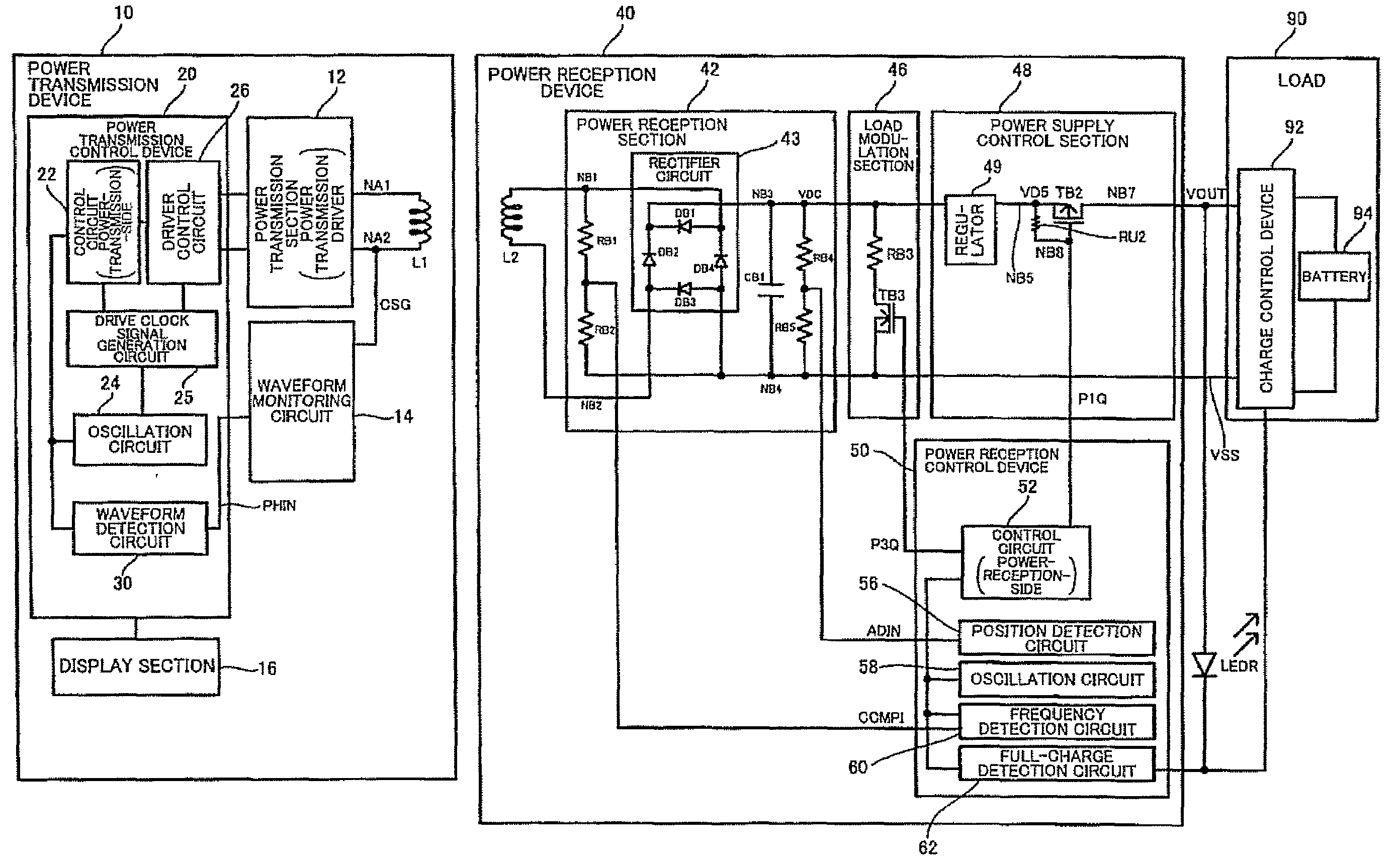
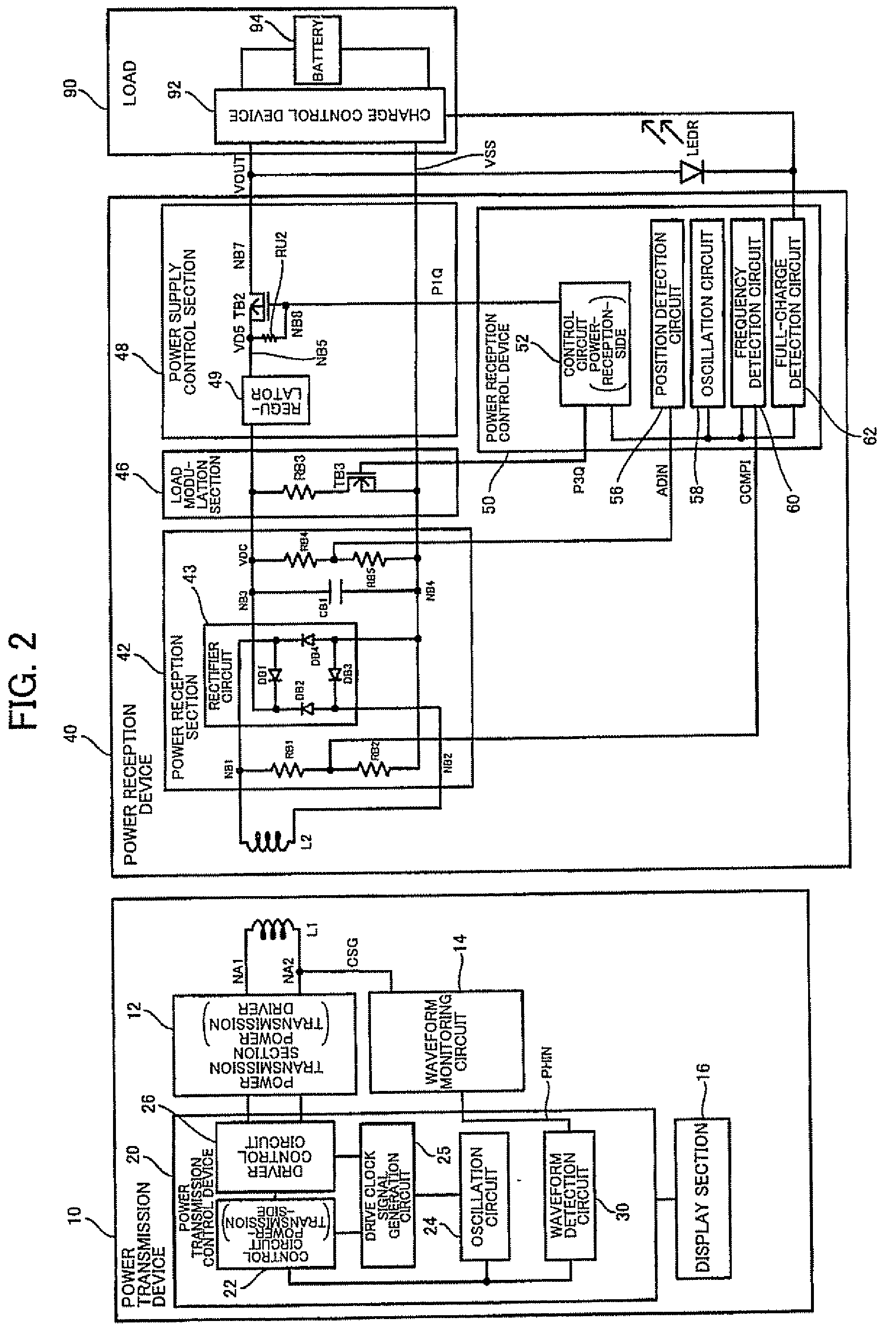
[0043]Several aspects of the invention may provide a power transmission control device, a power transmission device, an electronic instrument, and a non-contact power transmission system capable of appropriately detecting a power-reception-side load state.

[0044]According to one embodiment of the invention, there is provided a power transmission control device provided in a power transmission device included in a non-contact power transmission system, the non-contact power transmission system transmitting power from the power transmission device to a power reception device by electromagnetically coupling a primary coil and a secondary coil to transmit the power to a load of the power reception device, the power transmission control device comprising:

[0045]a drive clock signal generation circuit that generates a drive clock signal that specifies a drive frequency of the primary coil;

[0046]a driver control circuit that generates a driver control signal based on the drive clock signal, ...


PUM


Abstract

A power transmission control device provided in a power transmission device of a non-contact power transmission system includes a drive clock signal generation circuit that generates a drive clock signal, a driver control circuit that generates a driver control signal based on the drive clock signal, a waveform detection circuit, and a control circuit. The waveform detection circuit includes a pulse width detection circuit that measures a first pulse width period to detect first pulse width information, the first pulse width period being a period between a first edge timing of the drive clock signal and a first timing, the first timing being a timing when a first induced voltage signal that has changed from a low-potential-side power supply voltage exceeds a first threshold voltage. The control circuit detects the power-reception-side load state based on the first pulse width information.

Description

[0001]Japanese Patent Application No. 2007-171345 filed on Jun. 29, 2007 and Japanese Patent Application No. 2007-184206 filed on Jul. 13, 2007, are hereby incorporated by reference in their entirety.BACKGROUND OF THE INVENTION[0002]The present invention relates to a power transmission control device, a power transmission device, an electronic instrument, a non-contact power transmission system, and the like.[0003]In recent years, non-contact power transmission (contactless power transmission) that utilizes electromagnetic induction to enable power transmission without metal-to-metal contact has attracted attention. As application examples of non-contact power transmission, charging a portable telephone, charging a household appliance (e.g., cordless telephone handset), and the like have been proposed.[0004]JP-A-2006-60909 discloses related-art non-contact power transmission. JP-A-2006-60909 implements data transmission from a power reception device (secondary side) to a power trans...

Claims


Application Information

Patent Timeline
IPC IPC(8): H02J1/00H01F38/14
CPCH02J7/0011H02J7/045H02J7/025H02J7/0034H02J7/04H02J50/80H02J50/90H02J50/12H02J7/007182H02J50/60H02J50/10H02J7/00
Inventor IISAKA, KENJIN, MIKIMOTO
Owner SEIKO EPSON CORP
Why Eureka
Try Eureka