Ignition controller, light source, projector and ignition control method

a technology of ignition control and light source, which is applied in the direction of electric variable regulation, process and machine control, instruments, etc., can solve the problems of affecting unable to apply current rapidly to electrodes, and damage to electrodes, so as to improve the light-emitting efficiency of discharge lamps, the effect of preventing damag

Active Publication Date: 2009-01-01
SEIKO EPSON CORP
View PDF9 Cites 17 Cited by
  • Summary
  • Abstract
  • Description
  • Claims
  • Application Information

AI Technical Summary

Benefits of technology

[0034]Specifically, the pulse applying step applies the high pressure pulse, the direct current applying step applies the direct current to each electrode of the discharge lamp during the first period. Therefore, since sufficient electrical power is can be applied during the glow discharge period, the temperature increase in the electrodes and the evaporation of the mercury adhered to the electrode can be accelerated, thereby promoti

Problems solved by technology

However, in the high-pressure discharge lamp ignition device disclosed in Document 1, it is difficult to apply the current rapidly to the electrodes as in actuation by the direct current, since the alternating current voltage is applied to the discharge lamp when the lamp is actuated.
Consequently, a current sufficient for raising the temperature cannot be applied to the electrodes.
Such asymmetrical current may damage the electrodes.
Additionally, when the temperature of the electrodes does not rapidly increase, the transition from the glow discharge period to the arc discharge period delays.
This also may cause the damage to the electrodes.
On the other hand, when the above period is longer than 500 msec, the electrodes of the discharge lamp may be damaged.
When the frequency of the alternating current applied to the discharge lamp during the second period is 10 Hz or lower, the discharge lamp may not be suitably lit and the electrode

Method used


Image

  • Ignition controller, light source, projector and ignition control method
  • Ignition controller, light source, projector and ignition control method
  • Ignition controller, light source, projector and ignition control method

Examples


Embodiment Construction

)

[0042]An embodiment of the invention will be described below with reference to the attached drawings.

[0043][Arrangement of Projector 1]

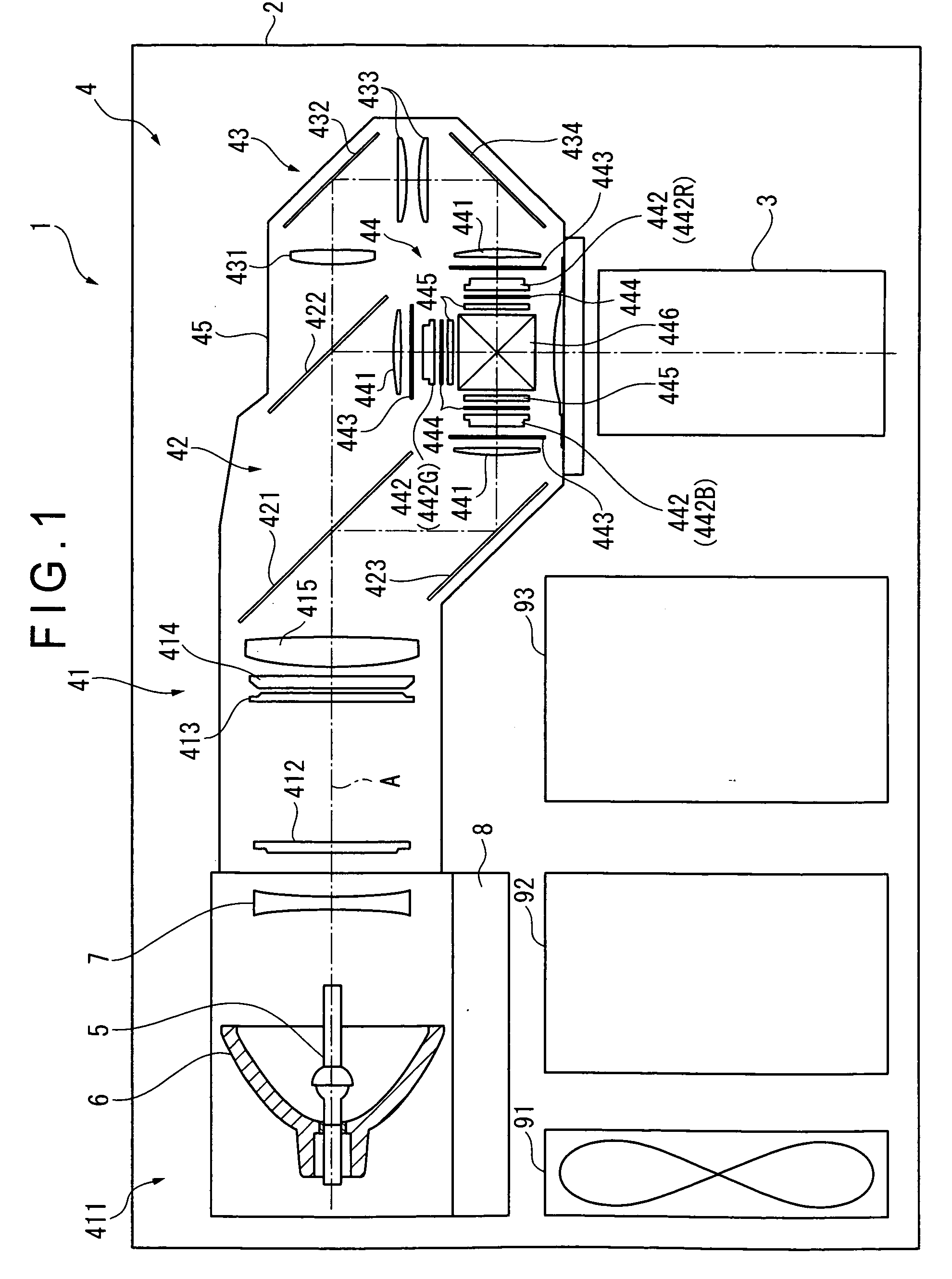
[0044]FIG. 1 is a schematic view showing an outline arrangement of a projector 1 according to an exemplary embodiment of the invention.

[0045]The projector 1 modules a light beam irradiated from a light source 411 in accordance with image information to form image light, and projects an image of the image light on a projection surface such as a screen (not shown) in an enlarged manner. As shown in FIG. 1, the projector 1 includes an exterior casing 2, a projection lens 3 and an optical unit 4.

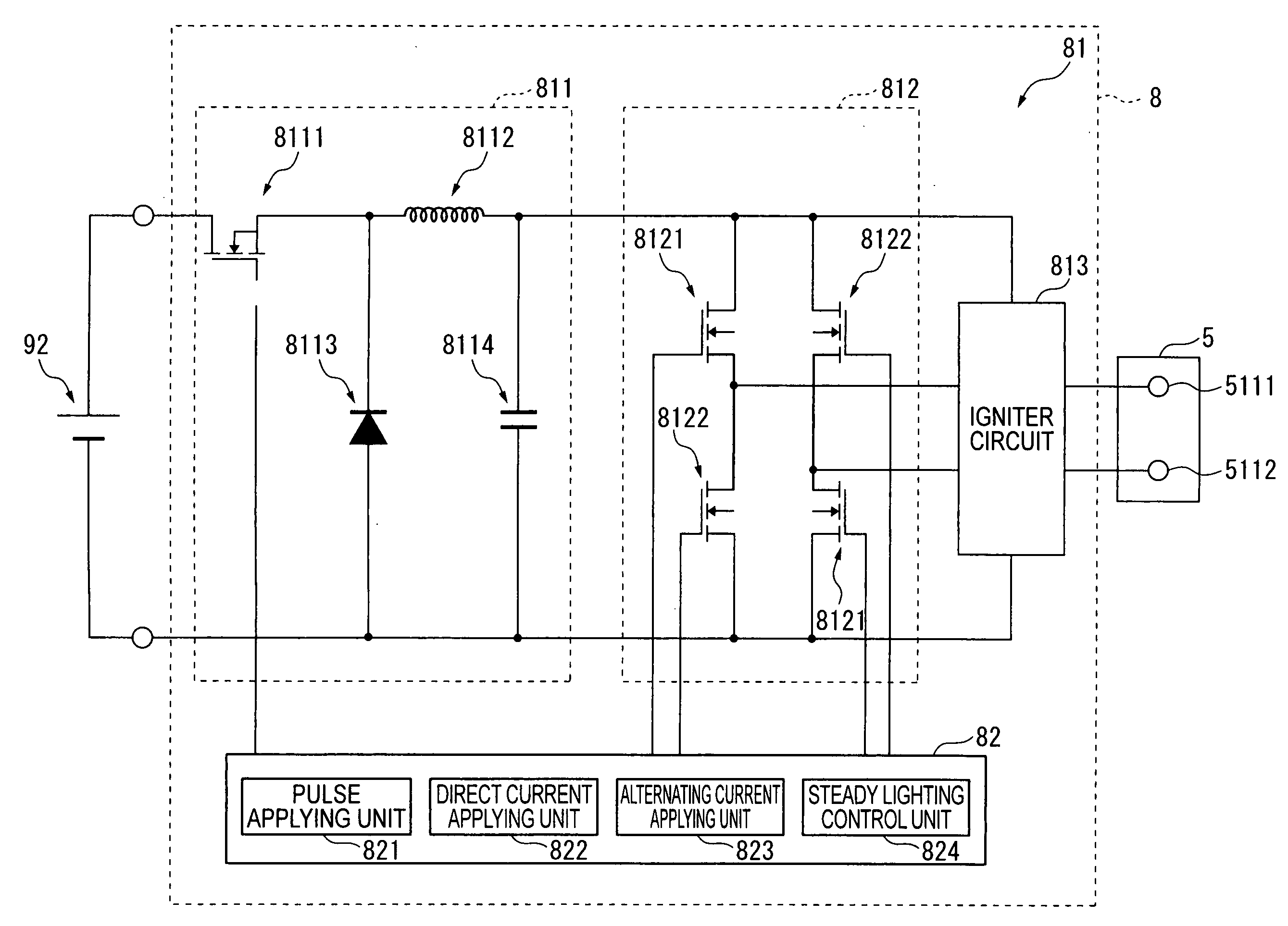
[0046]The projector 1 also includes a cooling unit 91 having a cooling fan for cooling inside of the projector 1, a power supply unit 92 for supplying electrical power to each component in the projector 1, a control unit 93 for controlling the whole projector 1. These components are all disposed in the exterior casing 2.

[0047]The power supply unit 92 converts a ...


PUM


Abstract

An ignition controller that controls ignition of a discharge lamp discharging and emitting light between a pair of electrodes provided therein, the controller includes: an ignition device that ignites the discharge lamp, and a controller that controls a drive of the ignition device, in which the controller includes: a pulse applying unit that applies a high pressure pulse to the pair of electrodes by the ignition device, a direct current applying unit for applying a direct current to the pair of electrodes for a first period after applying the high pressure pulse, and an alternating current applying unit for applying a first alternating current to the pair of electrodes for a second period after the first period.

Description

[0001]The entire disclosure of Japanese Patent Application No. 2007-171781, filed Jun. 29, 2007, is expressly incorporated by reference herein.BACKGROUND[0002]1. Technical Field[0003]The invention relates to an ignition controller that controls ignition of a discharge lamp discharging and emitting light between a pair of electrodes provided therein, a light source, a projector, and an ignition control method for the discharge lamp.[0004]2. Related Art[0005]A discharge lamp such as an extra-high pressure mercury lamp including a light-emitting tube having a light-emitting portion provided with a discharge space in which a pair of electrodes are disposed, and a pair of sealing portions which extend away from each other sandwiching the light-emitting portion and are provided with an electrode-connecting wire has been traditionally known. In the discharge space of such discharge lamp, light-emitting materials such as mercury and rare gas are sealed. The mercury is adhered to easier-to-b...

Claims


Application Information

Patent Timeline
IPC IPC(8): H05B41/36
CPCY02B20/202H05B41/2888Y02B20/00
Inventor OKAWA, KAZUO
Owner SEIKO EPSON CORP
Why Eureka
Try Eureka