
Cleaning blade member

a cleaning blade and blade technology, applied in the field of cleaning blade members, can solve the problems of edge drooping, surface drooping of cleaning blades, and unsatisfactory wear resistance and edge drooping resistance, and achieve excellent wear resistan

Active Publication Date: 2009-01-01
SYNZTEC
View PDF1 Cites 33 Cited by
  • Summary
  • Abstract
  • Description
  • Claims
  • Application Information

AI Technical Summary

Benefits of technology

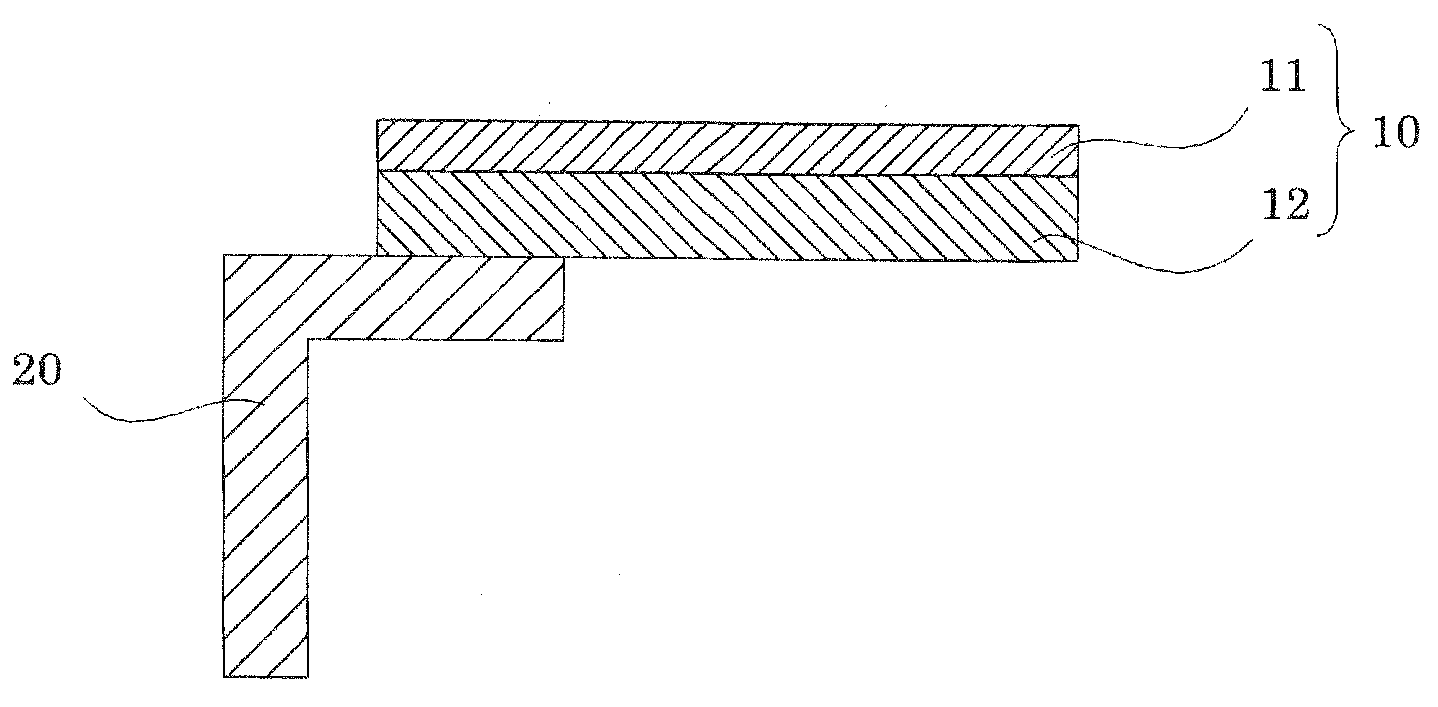
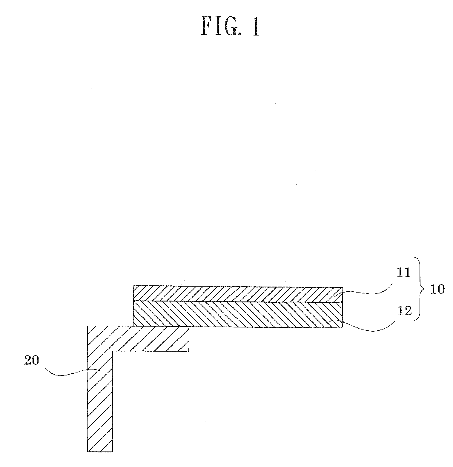
The present invention provides a high-durability cleaning blade member that has excellent wear resistance and edge droop resistance. This is achieved by using a polyurethane member produced through curing and molding a castable polyurethane composition containing a long-chain polyol, a polyisocyanate, and a diamino compound having a melting point of 80° C. or lower. The elastic layer is produced using a polyurethane member produced through curing and molding a castable polyurethane composition containing a long-chain polyol, a polyisocyanate, a short-chain diol, and a short-chain triol. The overall Young's modulus of the cleaning blade layer and the elastic layer is 5.0 to 14.0 MPa. The invention also provides specific embodiments of the cleaning blade member with improved wear resistance and edge droop resistance.

Problems solved by technology

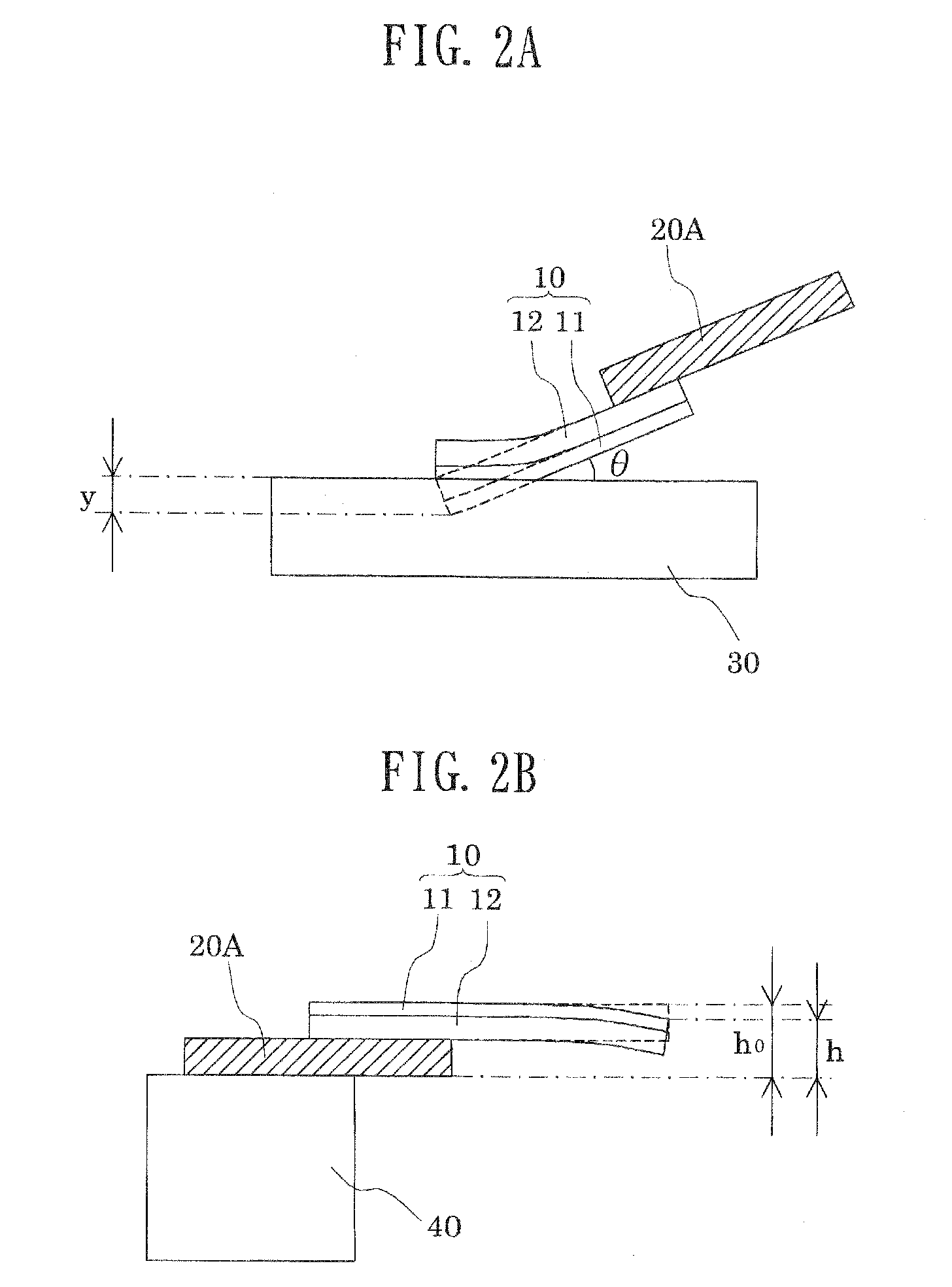
However, when the hardness of a conventional single-layer cleaning blade is increased, excessive pressure is applied to a photoreceptor, resulting in exfoliation of a surface layer of the photoreceptor or edge drooping of the cleaning blade, which is problematic.
However, wear resistance and edge droop resistance are still unsatisfactory and are to be further improved.

Method used


Image

  • Cleaning blade member
  • Cleaning blade member
  • Cleaning blade member

Examples


example 1

[0068]The materials for forming polyurethane D and those for forming polyurethane A were sequentially fed to a centrifugal molding machine in predetermined amounts, and centrifugal casting was performed, whereby a cleaning blade member having a cleaning layer (thickness: 0.5 mm) made of polyurethane A and an elastic layer (thickness: 1.5 mm) made of polyurethane D was produced. The cleaning blade member was cut into pieces, and each piece was bonded to a metal plate (support member), to thereby form a cleaning blade of Example 1.

example 2

[0069]The procedure of Example 1 was repeated, except that the materials for forming polyurethane E and those for forming polyurethane B were sequentially fed to a centrifugal molding machine in predetermined amounts, and centrifugal casting was performed, whereby a cleaning blade member having a cleaning layer (thickness: 0.5 mm) made of polyurethane B and an elastic layer (thickness: 1.5 mm) made of polyurethane E was produced, to thereby form a cleaning blade of Example 2.

example 3

[0070]The procedure of Example 1 was repeated, except that the materials for forming polyurethane F and those for forming polyurethane C were sequentially fed to a centrifugal molding machine in predetermined amounts, and centrifugal casting was performed, whereby a cleaning blade member having a cleaning layer (thickness: 0.5 mm) made of polyurethane C and an elastic layer (thickness: 1.5 mm) made of polyurethane F was produced, to thereby form a cleaning blade of Example 3.


PUM


Abstract

A cleaning blade member includes a cleaning layer and an elastic layer provided on the cleaning layer's back surface. Both are formed of a polyurethane member produced through curing and molding a castable polyurethane composition, the cleaning layer containing a long-chain polyol, a polyisocyanate, and a diamino compound having a melting point ≦80° C., the elastic layer containing a long-chain polyol, a polyisocyanate, a short-chain diol, and a short-chain triol, and has a percent edge drooping ≦7.0%, the cleaning and elastic layers have Young's modulus contribution factors Ra and Rb, respectively. (Rb / Ra)=0.05-6.0. Ra=[TaEa / (Ta+Tb)]. Rb=[TbEb / (Ta+Tb)]. Ea and Eb are Young's modulus of the cleaning and elastic layers, respectively. Ta and Tb represent the thicknesses of the cleaning and elastic layers, respectively, and the overall Young's modulus of the cleaning layer and elastic layer is (Ra+Rb)=5.0-14.0 MPa.

Description

[0001]The entire disclosure of Japanese Patent Applications Nos. 2007-168182 filed on Jun. 26, 2007 and 2008-162881 filed on Jun. 23, 2008 is expressly incorporated by reference herein.BACKGROUND OF THE INVENTION[0002]1. Field of the Invention[0003]The present invention relates to a cleaning blade member and, more particularly, to a cleaning blade member for removing toner deposited on a toner image carrier employed in an electrophotographic process such as a photoconductor or a transfer belt, on which a toner image is formed and which transfers the formed image to an image receptor.[0004]2. Background Art[0005]Generally, in an electrophotographic process, electrophotographic apparatus parts such as an electrophotographic photoreceptor and a transfer belt are used cyclically and repeatedly, and toner deposited thereon is removed by means of a cleaning blade. The cleaning blade, which generally comes into contact with a photoreceptor over a long period of time, is required to have ex...

Claims


Application Information

Patent Timeline
Patent Type & Authority Applications(United States)
IPC IPC(8): G03G21/00
CPCG03G21/0017G03G2221/0005
Inventor UENO, MIYUKIABE, SHUJINODA, SHUHEI
Owner SYNZTEC
Learn More